
Related Manuals for MSA ALTAIR 2X


Summary of Contents for MSA ALTAIR 2X
- Page 1 Operating Manual ALTAIR® 2X Single or Two Gas Detector Order No.: 10148950/07 Print Spec: 10000005389 (EO) CR: 800000059385 MSAsafety.com...
- Page 2 The warranties made by MSA with respect to the product are voided if the product is not installed and used in accordance with the instructions in this manual. Please protect yourself and your employees by following the instructions.
-
Page 3: Table Of Contents
Contents Safety Regulations Correct Use Liability Information Safety and Precautionary Measures Warranty Description Overview On-Screen Indicators Sensor End of Life Warning Sensor End of Life Alarm Backlight Fresh Air Setup (FAS) Bump Test for Sensors with XCell Pulse Technology Environmental Factors Settings First Use Turning ON the Device... - Page 4 Ordering Information Calibration Gas Cylinders Replacement Parts and Accessories Sensor Replacement Kits ALTAIR® 2X...
-
Page 5: Safety Regulations
Safety Regulations Correct Use The ALTAIR 2X gas detector, hereafter referred to as device, is intended for use by trained and qualified personnel. It is designed to be used when performing a hazard assessment to: • Assess potential worker exposure to toxic gases and vapors. - Page 6 Bump test frequency is often stipulated by national or corporate regulations; however, bump testing before each day's use is generally the accepted best safety practice and is therefore MSA’s recommendation. The device must pass the bump test. If it fails the test, perform a calibration before using the device.
-
Page 7: Warranty
1 Safety Regulations Be Aware of the Warranty Regulations The warranties made by Mine Safety Appliances Company with respect to the product are voided if the product is not used and maintained in accordance with the instructions in this manual. Please protect yourself and others by following them. We encourage our customers to write or call regarding this equipment prior to use or for any additional information relative to use or service. -
Page 8: Description
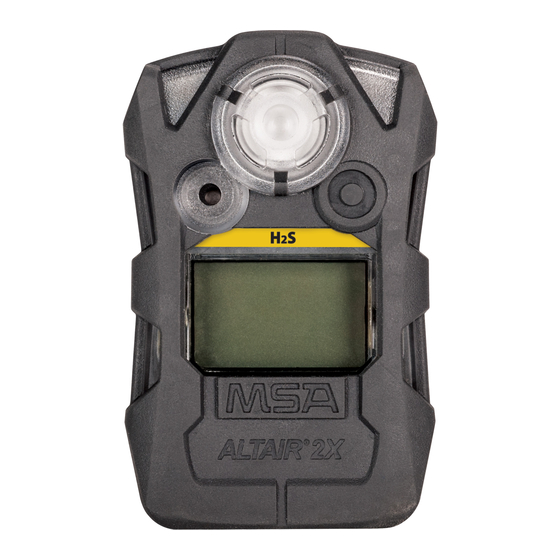
2 Description Description Overview Figure 1 Device view Alarm LED (red) Button Infrared port Display with backlight Sensor cover Gas type Safe LED (green) Audible alarm transmitter The device monitors gases in ambient air and in the workplace. The following toxic gases can be monitored in the ambient air: •... - Page 9 S/SO The alarm levels for the individual gases are factory-set and and cannot be changed during operation. Changes can only be made through MSA Link software. Short Term Exposure Limits (STEL) The STEL alarm is calculated over a 15 minute exposure.
-
Page 10: On-Screen Indicators
2 Description On-Screen Indicators Figure 2 Display Only displayed for two gas detectors. The label above this bar shows which gas concentration is currently displayed Sensor life Symbol – Indicates the end of sensor life Bump Check Symbol – Indicates successful bump test or calibration Alarm Symbol –... -
Page 11: Sensor End Of Life Warning
2 Description Flow check symbol - Indicates that a flow check is being prepared or should be executed Battery condition - Indicates the battery charge level Indicates a battery alarm when flashing Electronic pulse check symbol - Indicates a currently running electronic check of the sensor Indicates required interaction Gas concentration Volume percent... -
Page 12: Use
Zero the device at the work site temperature for the least effect. Settings Any changes of the device settings can only be carried out using the MSA Link™ software. Ensure that the latest version of the MSA Link software is used. -
Page 13: First Use
3 Use NOTE: When Sleep Mode is enabled, it is not possible to enable Motion Alert. Operating This operating beep activates every 30 seconds by momentarily beeping the horn under the following Beep conditions: • Operating beep is enabled • Device is in normal operating mode •... -
Page 14: Turning On The Device
• Alarm LEDs light • Vibrating alarm is activated. The device displays the following for a few seconds each: • MSA • Software version • WAIT (Displayed for up to 20 seconds during sensor discovery) • If enabled: individual alarm indication settings •... - Page 15 3 Use Figure 3 Startup 3. Fresh Air Setup prompt (FAS?)/Pulse Check start screen (PULSE) is displayed, depending on the sensor installed. ALTAIR® 2X...
- Page 16 3 Use WARNING! Only carry out the Fresh Air Setup/bump test in fresh, uncontaminated air; otherwise, inaccurate readings can falsely indicate a hazardous atmosphere as safe. If the quality of the surrounding air is uncertain, do not carry out a Fresh Air Setup/bump test.
- Page 17 3 Use Figure 4 Startup, continued FAS? is displayed. 1. To start the FAS press the button while FAS? is displayed. ALTAIR® 2X...
- Page 18 3 Use The display will show the results of the setup, PASS or ERR. The fresh air setup has limits. If a hazardous level of gas is present, the device displays ERR. Press the button to acknowledge the error and perform a calibration. Bump Test for Devices with XCell Pulse Technology This test will start automatically.
- Page 19 3 Use Figure 5 FAS (Devices without XCell Pulse technology) ALTAIR® 2X...
- Page 20 3 Use Figure 6 Bump test for devices with XCell Pulse technology ALTAIR® 2X...
- Page 21 3 Use 5. If Calibration Due (CAL DUE) is enabled via MSA Link™ software (default is OFF): • If calibration is due, CAL DUE will scroll across the display continuously. Press the button to proceed. A calibration is now necessary. • If calibration is not due, CAL, the number of days, and DAYS will scroll across the display once before proceeding.
-
Page 22: Function Checks Before Use
3 Use Figure 8 Measurement Function Checks Before Use Checking the Confidence Indicator The Confidence indicator must flash every 15 seconds after starting the device. This indicates the device is operating correctly. Verifying Alarms Verify that the audible, visual and vibrating alarms function. During the turn-on sequence, the alarms are briefly activated (function tests). - Page 23 Bump test frequency is often stipulated by national or corporate regulations; however, bump testing before each day's use is generally the accepted best safety practice and is therefore MSA's recommendation. Failure to follow this warning can result in serious personal injury or death.
- Page 24 3 Use Figure 9 Bump Test for devices without XCell Pulse technology Bump Test for Devices with XCell Pulse Technology Devices with XCell Pulse technology can be bump tested with a combination of a pulse check and a flow check. ALTAIR®...
-
Page 25: Duration Of Use
3 Use 1. Press the button for about 1 second. PULSE? is displayed. 2. Press the button again while PULSE? is displayed. 3. Follow the instructions in section Duration of Use Normal Operation The device is ready for operation • as long as the empty battery icon is not flashing empty and •... -
Page 26: Monitoring Gas Concentration
3 Use • battery outline indicator flashes • alarm icon turns ON • alarm sounds • alarm LEDs flash • no gas reading display • display alternates between BATT and ERR • no other device pages can be viewed The device remains in this state until it is turned OFF or the battery is completely depleted. The alarm lights and the audible alarm can be silenced by pushing the button. - Page 27 3 Use • the alarm symbol will display and flash • the icon for the type of alarm will display and flash • a vibrating alarm is triggered • an alarm sounds • alarm LEDs flash Low Alarm If the gas concentration reaches or exceeds the low alarm setpoint the device will: •...
-
Page 28: Changing Alarm Setpoints
Refer to the device during test mode for factory-set alarm setpoints. Changing Alarm Setpoints Alarm setpoints can only be changed using the MSA Link™ Software. Displaying Device Data The Information page can be accessed by pushing the button for over one second. -
Page 29: Ir Mode
3 Use Figure 10 Displaying device data 3.10 IR mode A button press in measurement mode will activate IR mode for 1 minute. If no IR communications are detected, the device will exit this mode automatically. ALTAIR® 2X... -
Page 30: Turning Off The Device
MSA recommends a calibration interval of 2 months for devices with XCell Pulse technology and a maximum 6 months for devices with standard XCell sensors. - Page 31 3 Use Devices must be calibrated: • after subjected to physical shock, • after any extreme changes in the atmospheric temperature, • after use under high gas concentrations, • if the bump test/FAS failed, • at certain intervals by local procedures. Calibration mode can be entered after the info screens have been displayed (see Figure 10 1.
- Page 32 3 Use whether the test gas cylinder is empty or the date has expired, whether the test gas hose was connected to the sensor, whether the flow regulator is set to 0.25 l/min. 7. If necessary, repeat steps (1) to (6). PASS is displayed.
- Page 33 3 Use Figure 11 Zero calibration ALTAIR® 2X...
- Page 34 3 Use Figure 12 Span calibration ALTAIR® 2X...
-
Page 35: Using The Device With A Galaxy Gx2 Automated Test System
3 Use Figure 13 Pulse check after calibration for devices with XCell Pulse technology 3.14 Using the Device with a GALAXY GX2 Automated Test System 1. Press the button on the device to enter IR mode. The device pages begin to display. 2. -
Page 36: Maintenance
If the error occurs during the warranty period, please contact the MSA customer service. Otherwise, the device must be put out of operation. Some errors will show an additional error code number which should be noted and be available when contacting MSA. -
Page 37: Replacing The Battery
4 Maintenance Replacing the Battery WARNING! Risk of explosion: Do not change batteries in hazardous areas. Failure to follow this warning can result in serious personal injury or death. Only replace with battery as listed in section 7 Figure 14 Sensor and Battery Replacement Sensor Battery 1. -
Page 38: Replacing The Sensor
After replacing the battery or if the device was without power for some time, it is necessary to set time and date again using the MSA Link software. Failure to follow this caution can result in minor or moderate injury. -
Page 39: Cleaning
4 Maintenance CAUTION! Do not over-tighten the screws; otherwise, the case may be damaged. Failure to follow this caution can result in minor or moderate injury. 7. Reinstall the screws, tighten with a torque value of 2.5 in-lbs (0.28 Nm). WARNING! Calibration is required after a sensor is installed;... -
Page 40: Technical Data
5 Technical Data Technical Data Technical Specifications Weight 115 g (4 oz) (device with battery and clip) Dimensions(L x W x 87 x 55 x 48 mm (3.4 x 2.2 x 1.9 in) – with fastening clip Alarms Two super bright LEDs with 320° viewing angle and a loud audible alarm, vibrating alarm Volume of 95 dB typical at 30 cm distance audible alarm... - Page 41 5 Technical Data Sensor Low Alarm High Alarm - Minimum Alarm Maximum Alarm STEL Set Point Setpoint -Setpoint -Setpoint CO Carbon Monoxide High 25 ppm 100 ppm 10 ppm 8500 ppm Concentration S Hydrogen Sulfide 10 ppm 15 ppm 5 ppm 175 ppm 15 ppm 10 S Low Concentration...
-
Page 42: Data Logging Specifications
Session Number of Greater than 300 (most recent occurrences) data log stored events ® Data Via MSA infrared adapter on a PC using MSA Link™ software transmission method Event log Alarm - Alarm Type - Alarm Value - Time/Date information Alarm Clear - Alarm Type - Alarm Value - Time/Date... - Page 43 5 Technical Data estimate single gas devices with default interval (storage time varies based on interval and sensor activity) Transmission Dependent on number of records. time ALTAIR® 2X...
-
Page 44: Certification
6 Certification Certification See device label for the certification that applies to the specific device. Country Exia Class I, Groups A, B, C, D Class II, Groups E, F, G Class III Ambient temperature: -40 °C to +60 °C; T4 Canada Exia Class I, Groups A, B, C, D Class II, Groups E, F, G Class III... -
Page 45: Marking, Certificates And Approvals According To The Directive 2014/34/Eu (Atex)
6 Certification Marking, Certificates and Approvals According to the Directive 2014/34/EU (ATEX) MSA The Safety Company Manufacturer: 1000 Cranberry Woods Drive Cranberry Township, PA 16066 USA Product: EC-Type Examination Certificate: FTZU 13 ATEX 0200 X EN 60079-0: 2012+A11:2013, Type of protection:... -
Page 46: Marking, Certificates And Approvals According To Iecex
6 Certification Marking, Certificates and Approvals According to IECEx MSA The Safety Company Manufacturer: 1000 Cranberry Woods Drive Cranberry Township, PA 16066 USA Product: IECEx-Type Examination -Certificate: IECEx FTZU 13.0025X IEC 60079-0: 2017, Type of protection: IEC 60079-11: 2011 Performance... - Page 47 7 Ordering Information Ordering Information Calibration Gas Cylinders Description Part Number N.A. Cylinder, 60 ppm CO, 34 L 710882 10073231 Cylinder, 60 ppm CO, 20 ppm H S, 34 L 10153800 10154976 Cylinder, 60 ppm CO, 20 ppm H S, 58 L 10153801 10154977 Cylinder, 60 ppm CO, 20 ppm H...
- Page 48 7 Ordering Information Description Part Number MSA Link IR Dongle with USB connector 10082834 Horn and Sensor Gasket 10152337-SP Battery (Pack of 8) 10155203-SP Screws, Case (Pack of 40) 10153060-SP Front Case Replacement Assembly with Gaskets and Display (without front label) •...
- Page 49 7 Ordering Information Description Part Number S-PLS replacement kit, XCell sensor 10121227 low power, replacement kit, XCell 10152601 sensor /CO low power, replacement kit, XCell 10152606 sensor ALTAIR® 2X...
- Page 50 For local MSA contacts, please visit us at MSAsafety.com...
Need help?
Do you have a question about the ALTAIR 2X and is the answer not in the manual?
Questions and answers