
Related Manuals for Ingecon SUN STORAGE 100TL

Summary of Contents for Ingecon SUN STORAGE 100TL
- Page 1 INGECON SUN STORAGE 100TL Uso y configuración del ISS 100TL conectado a la batería 5K3 XP de WECO Use and Settings of the ISS 100TL working with the battery 5K3 XP of WECO...
-
Page 2: Table Of Contents
INTRODUCCIÓN ............................ 3 BATERÍA 5K3 XP ............................ 4 UNA ÚNICA TORRE DE BATERÍAS ....................4 2.1.1 Conexión de los cables DC de la batería ................. 4 2.1.2 Conexión de los cables DC de la batería al inversor ............... 5 2.1.3 Conexión del cable de comunicaciones CAN entre los módulos de baterías ...... -
Page 3: Introducción
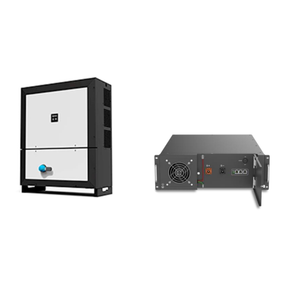
Ingeteam 1. INTRODUCCIÓN Este documento describe el proceso para conectar y configurar el inversor INGECON SUN STORAGE 100TL (ISS 100TL) para trabajar con la batería 5K3 XP de WECO. 5K3 XP ISS 100TL Combiner Box HV BOX La versión mínima del ISS 100TL para que pueda trabajar con la batería 5K3 XP es la siguiente: Versión mínima del ISS 100TL:... -
Page 4: Batería 5K3 Xp
Ingeteam 2. BATERÍA 5K3 XP Este capítulo describe el proceso de conexión, encendido y configuración del ISS 100TL para trabajar con la batería 5K3 XP. Dependiendo del número de torres de baterías en paralelo, las conexiones se realizarán de una manera o de otra. -
Page 5: Conexión De Los Cables Dc De La Batería Al Inversor
Ingeteam 2.1.2 Conexión de los cables DC de la batería al inversor Por favor, tener en cuenta las siguientes recomendaciones técnicas: 1) El inversor tiene que estar apagado antes de conectar las baterías. 2) El cableado DC debe tener una sección entre 12-35mm El cableado de DC debe tener terminales en el lado del inversor. -
Page 6: Conexión Del Cable De Comunicaciones Can Entre Los Módulos De Baterías
Ingeteam 2.1.3 Conexión del cable de comunicaciones CAN entre los módulos de baterías La comunicación entre los módulos se debe hacer uniendo el puerto CAN-A con el puerto CAN- B del siguiente módulo. Del primer módulo habrá que unir el puerto CAN-B al puerto CAN 1-B de la HV BOX. - Page 7 Ingeteam Esto se puede hacer, por ejemplo, con un cable Ethernet. Conectando el conector RJ45 del cable en el puerto de la HV BOX. Además, el DIP Switch de la HV BOX que está comunicándose con el inversor tiene que estar en esta posición: Por otro lado, el ISS 100TL requiere de un cable CAN de dos hilos.
- Page 8 Ingeteam ISS 100TL 1. Introducir el cableado de comunicación CAN a través del pasacables destinado a este uso. 2. Conectar el cableado en el terminal J76 tal y como indica la figura anterior, respetando las indicaciones impresas en la serigrafía de la tarjeta electrónica (CAN_L, CAN_H).
-
Page 9: Dos O Más Torres De Baterías
Ingeteam 2.2 DOS O MÁS TORRES DE BATERÍAS Para ese tipo de instalaciones se necesitará una HV BOX por cada torre de baterías que se vayan a poner en serie, una Combiner Box para realizar el paralelizado de la DC, una fuente de 24V para alimentar la Combiner Box y los módulos de batería deseados para poner en serie. -
Page 10: Conexión De Los Cables Dc De La Batería Al Inversor
Ingeteam Además, hay que puentear las DI2 de las HV BOX y la DO1 de la Combiner BOX DI2 HV BOX DO1 Combiner BOX 2.2.2 Conexión de los cables DC de la batería al inversor Por favor, tener en cuenta las siguientes recomendaciones técnicas: 1) El inversor tiene que estar apagado antes de conectar las baterías. -
Page 11: Conexión Del Cable De Comunicaciones Can Entre Los Módulos De Baterías
Ingeteam 2.2.3 Conexión del cable de comunicaciones CAN entre los módulos de baterías La comunicación entre los módulos se hace uniendo el puerto CAN-A con el puerto CAN-B del siguiente módulo. Del primer módulo habrá que unir el puerto CAN-B al puerto CAN 1-B de la HV BOX. -
Page 12: Conexión Del Cable De Comunicaciones Can Entre Batería E Inversor
Ingeteam 2.2.4 Conexión del cable de comunicaciones CAN entre batería e inversor La comunicación entre la batería y el inversor se hace mediante un cable de comunicación que conecte el puerto CAN 2/INVERTER de la Combiner Box con el inversor. Esto se puede hacer, por ejemplo, con un cable Ethernet. - Page 13 Ingeteam Una vez identificados los pines 7 y 8, los dos hilos se tienen que conectar en la borna J76 del inversor tal y como se detalla a continuación: ISS 100TL 1. Introducir el cableado de comunicación CAN a través del pasacables destinado a este uso.
-
Page 14: Encender Inversor
Ingeteam 2.3 Encender inversor El inversor se puede encender alimentándolo desde la batería WECO 5K3 XP, sin que previamente así se haya configurado. Para usar está función, seguir los siguientes pasos: • UNA ÚNICA BATERÍA EN PARALELO 1. Encender todos los módulos de las baterías. 2. -
Page 15: Revisión Final
Ingeteam 3. REVISIÓN FINAL En este capítulo se describen las instrucciones para revisar que la conexión y la configuración se han realizado correctamente. 1) Verificar que el cable de comunicaciones CAN está conectado a la batería y al inversor. 2) Verificar que el inversor está encendido. 3) Al acceder al inversor, verificar que no muestra alarma “Communication Error with BMS”. - Page 16 INTRODUCTION ..........................17 5K3 XP BATTERY ..........................18 ONE TOWER OF BATTERIES ......................18 2.1.1 Wiring of Battery DC wire ..................... 18 2.1.2 Wiring of DC wires from battery to inverter................. 19 2.1.3 Wiring of CAN communication cable between battery modules ......... 20 2.1.4 Wiring of the CAN communication cable between battery and inverter ......
-
Page 17: Introduction
Ingeteam 1. INTRODUCTION This document describes the process for connecting and configuring the INGECON SUN STORAGE 100TL (ISS 100TL) to work with the battery 5K3 XP of WECO. 5K3 XP ISS 100TL Combiner Box HV BOX The minimum version of the ISS 100TL working with the 5K3 XP: Minimum Firmware Version for the ISS 100TL: •... -
Page 18: K3 Xp Battery
Ingeteam 2. 5K3 XP BATTERY This chapter describes the process of connection, switch on and configuration of the ISS 100TL to work with 5K3 XP battery. Depending on the number of batteries in parallel, the connections will be done in different ways. 2.1 ONE TOWER OF BATTERIES For this type of installations, a HV BOX and the desired battery modules will be necessary. -
Page 19: Wiring Of Dc Wires From Battery To Inverter
Ingeteam 2.1.2 Wiring of DC wires from battery to inverter Please, consider the following technical notes: 1) The inverter must be OFF before connecting the battery to the inverter. 2) Connect the DC power wires with a section between 12-35mm DC wiring must have terminals on the inverter side. -
Page 20: Wiring Of Can Communication Cable Between Battery Modules
Ingeteam 2.1.3 Wiring of CAN communication cable between battery modules The communication between modules must connect the CAN-A port with the CAN-B port of the next modules. The CAN-B port of the first module must be connected to the CAN 1-B of the HV BOX. - Page 21 Ingeteam This can be done, for example, with an Ethernet wire. Connecting the RJ45 connector of the wire to the HV BOX connector. Also, the DIP Switch of the HV BOX that is communicating with the inverter must be in this position: On the other hand, the ISS 100TL requires a two-wire CAN cable.
- Page 22 Ingeteam ISS 100TL 1. Pass the CAN communication cable through the dedicated cable gormet. 2. Connect both wires to the terminal J76 as shown in the previous figure, respecting the printed instructions on the screen-printed electronic card (CAN_L, CAN_H): Cable Ethernet ISS 100TL Pin 1 J76 CAN_L...
-
Page 23: Two Or More Tower Of Batteries
Ingeteam 2.2 TWO OR MORE TOWER OF BATTERIES For this type of installations, a HV BOX for each battery tower, a Combiner Box for the parallelization of the DC and the desired battery modules will be necessary. 2.2.1 Wiring of Battery DC wire The battery modules must be connected so the positive and negative end in the B+ and B- terminals of the HV BOX. -
Page 24: Wiring Of Dc Wires From Battery To Inverter
Ingeteam Also, DI2 of the HV BOX and DO1 of the Combiner Box must be short circuited. DI2 HV BOX DO1 Combiner BOX 2.2.2 Wiring of DC wires from battery to inverter Please, consider the following technical notes: 1) The inverter must be OFF before connecting the battery to the inverter. 2) Connect the DC power wires with a section between 12-35mm DC wiring must have terminals on the inverter side. -
Page 25: Wiring Of Can Communication Cable Between Battery Modules
Ingeteam 2.2.3 Wiring of CAN communication cable between battery modules The communication between modules must connect the CAN-A port with the CAN-B port of the next modules. The CAN-B port of the first module must be connected to the CAN 1-B of the HV BOX. -
Page 26: Wiring Of The Can Communication Cable Between Battery And Inverter
Ingeteam 2.2.4 Wiring of the CAN communication cable between battery and inverter The communication between battery and inverter must be done with a wire that connects CAN 2/INVERTER port of the Combiner Box with the inverter. This can be done, for example, with an Ethernet wire. Connecting the RJ45 connector of the wire to the CAN 2/INVERTER connector. - Page 27 Ingeteam ISS 100TL 1. Pass the CAN communication cable through the dedicated cable gormet. 2. Connect both wires to the terminal J76 as shown in the previous figure, respecting the printed instructions on the screen-printed electronic card (CAN_L, CAN_H): Cable Ethernet ISS 100TL Pin 8 J76 CAN_L...
-
Page 28: Switch On The Inverter
Ingeteam 2.3 Switch ON the inverter The inverter can be supplied from the 5K3 XP battery, without previous configuration. To do so, follow these steps: • ONE BATTERY IN PARALLEL 1. Switch ON all the battery modules. 2. Switch ON the HV BOX breaker and press Start button until it lights. 3. -
Page 29: Final Check
Ingeteam 3. FINAL CHECK This chapter describes the instructions to check that all the connections and settings have been successfully done. 1) Verify that the CAN communication cable from the battery to the inverter is connected. 2) Verify that the inverter is ON. 3) Access to the inverter and verify that there is no “Communication Error with BMS”...
Need help?
Do you have a question about the SUN STORAGE 100TL and is the answer not in the manual?
Questions and answers