Table of Contents
Advertisement
Quick Links
User manual for IPM5/IPW5-devices
Digital processor-controlled indication instrument for strain gauge measurement:
suitable for 4- or 6-wire measuring bridges (1.1mV/V; 2mV/V; 3.3mV/V; 6mV/V)
Panel meter with performance features as follows:
• adjustable input amplification for 1 mV/V, 2 mV/V or 3.3mV/V sensors
• 10 V integrated bridge supply for standard 350 ohm measuring bridges
• permanent wire-breach monitoring
• bipolar input range for compression and tensile forces
• integrated factory calibration for pre-calibrated weighing cells
• auto-sensor recognition for 1 mV/V, 2 mV/V and 3.3 mV/V
• measuring rate up to 50 measurements (measuring time adjustable from 0.02 to 10.000 sec)
• 24 bit transducer resolution, of which up to 19 bits (500,000 / 0.0002 % of measuring range),
are noise-free!
• high long-term and temperature stability
• 5-digit digital display with range from -9999 to 99999 digits
• free scaling and setting of decimal point
• alignment of a sensor with up to 30 additional calibration points
• tare function for manual and automatic control
• fully automatic or semi-automatic calibration functions
• min/max-value recording, can be called up or shown permanently in the display
• integrated conversion function with adjustable factor
• complex parameter and access security via several user levels with event counter
Advertisement
Table of Contents

Subscribe to Our Youtube Channel
Related Manuals for ICS IPM5


Summary of Contents for ICS IPM5
- Page 1 User manual for IPM5/IPW5-devices Digital processor-controlled indication instrument for strain gauge measurement: suitable for 4- or 6-wire measuring bridges (1.1mV/V; 2mV/V; 3.3mV/V; 6mV/V) Panel meter with performance features as follows: • adjustable input amplification for 1 mV/V, 2 mV/V or 3.3mV/V sensors •...
- Page 2 Identifizierung STANDARD TYPES ORDER NUMBER Supply 100-240 VAC 50/60 Hz, DC ±10% PM5.020X.1S70D PM5.020X.1W70D Supply 10-40 VDC galvanic isolated, 18-30 VAC 50/60 Hz Options – breakdown order code: P M 5. 0 2 0 X. 1 S 7 0 D Standard type Internal index version D...
-
Page 3: Table Of Contents
6.2 Alarms / Relays…………………………………………………………………… 6.3 Analog output……………………………………………………………………... 6.4 Digital input / Tara…….…………………………………………………….……. 6.4.1 Event counter………………………….…………………………..……… 6.4.2 Taring or calibration…..………………………………………………… 6.4.3 Adjustment with 80%-calibration (IPM5)…………………………..…..… 6.4.4 Sensitivity recognition …..………………………………………………… 6.4.5 Automatical calibration…………………………………………………… 6.4.6 Taring…….……………………………………...………………………… 6.4.7 Hold-function……………..……………………………………………… 6.5 Interfaces RS232 / RS485……….………………………………………………... -
Page 4: Brief Description
1. Brief description 1. Brief description With the IPM5 and IPW5 panel meters, sensor sizes can be directly recorded via strain gauges. For this purpose, the devices make an automatically controlled 10 V bridge supply available. The 5-digit display shows the measurement itself or the scaled value of the physical quantity. -
Page 5: Technical Data
0.1% of meas. range in controlled electromagnetic environment 0.75% of measuring range in industrial areas ± 2m V/V ± 1m V/V IPW5 > 10 MΩ Input resistance IPM5 approx. 5 kΩ Drift of temperature 20 ppm/K Measuring principle Sigma/Delta Measuring speed 0.01s…10.00s... - Page 6 2. Technical data Output Relay Switchover contact 250 VAC / 5A; 30 VDC / 5 A at ohm resistive burden Switching cycle 0.5 * 10 at maximum contact load 5 * 10 mechanically Division according to DIN EN 50178/Characteristics according to DIN EN 60255 Analog output 0/4-20 mA / burden <500 Ω, (galvanic isolated)
-
Page 7: Safety Advices
Please read the users guide before installation and keep it for future reference. Proper Use The IPM5/IPW5 device is designed for the evaluation and display of sensor signals. With the setpoints it is possible to perform simple control tasks. Danger! Careless use or improper operation can result in personal injury and/or damage the equipment. -
Page 8: Assembly
4. Assembly 4. Assembly Please read the Safety advices on page 5 before installation and keep this user manual for future reference. Gap for physical unit After removing the fixing elements, insert the device. Check the seal to make sure it fits securely. Click the fixing elements back into place and tighten the clamping screws by hand. -
Page 9: Electrical Connection
Data A (-) The lines of the RS232-interface need to be connected 1:1, TxD to TxD and RxD to RxD. IPW5 IPM5 IPW5/IPM5 Connection figure PC or SPS Interface RS485 is connected via a shielded data line with twisted wires (Twisted-Pair). - Page 10 However, as a rule, this generally leads to a loss of accuracy through the line impedance. At the input of the IPM5, a 4-wire sensor can be connected with a calibration wire (CAL). Sensor Strain gauge sensor...
-
Page 11: Connection Examples
In 2 In 3 In 4 In 5 In 6 In 7 100-240 VAC 0/4-20mA 0-10 VDC Measurement of a 4-wire sensor with a IPM5 with an actively switched digital input; auxiliary voltage 10-40 VDC: Important: The potential of the digital input is connected with the sensor potential. -
Page 12: Operation And Function Description
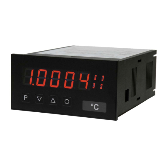
6. Operation and function description 6. Operation and function description 6.1. Operation Display (1) 7-segment display 5-digit, red Digit height 14 mm Display range -9999…99999 Positions after decimal point none, one, two, three, four (adjustable) Unit °C, °F, Pt100, thermocouple Switchpoint displays (2) Optical limit value report 4 LED, red... -
Page 13: Alarms / Relays
6. Operation and function description Switching on Before switching on check all electrical connections to make sure they are correct. On completion of the installation, the device can be switched on by applying the supply voltage. Starting sequence During the switching-on process, a segment test is performed for approx. 1 second, whereby all LED on the front (including switchpoint LED) are triggered. - Page 14 6. Operation and function description Operating current The setpoint is “off” below the threshold and “on” on reaching the threshold. Quiescent current The setpoint is “on” below the threshold and switched “off” on reaching the threshold. Switching-on delay The relay S1-S4 is “on” 10 seconds after reaching the threshold;...
-
Page 15: Analog Output
6. Operation and function description Optical response, display flashing The switching on of one or more setpoints can also be set to trigger a flashing of the display to enhance the optical response. Example: Let us assume the threshold for flashing of the display is set at setpoint 2. If setpoint 1 is exceeded and setpoint 2 is not, the setpoint LED 1 lights up permanently. -
Page 16: Adjustment With 80%-Calibration (Ipm5)
6. Operation and function decription 6.4.3 IPM5 calibration of mass pressure sensors Many standard sensors for mass pressure measurement have a special CAL wire. If this is connected to DMS-minus (Strain gauge minus), an unloaded bridge becomes so unbalanced that the signal value corresponds to an 80% load (80% is a standard value that can, however, be changed for the display). -
Page 17: Automatical Calibration
6. Operation and function description 6.4.5 Automatic calibration The IPM5 unit generally performs an automatic calibration. Depending on the setting, this can be triggered via the 4th key or the digital input. During calibration, the sensor must be free of pressure or the balance is without any load. Since, in the case of the IPW5, manual intervention is generally required, the semi-automatic calibration takes effect here. -
Page 18: Interfaces Rs232 / Rs485
6. Operation and function description 6.5 Interface All IPW5/IPM5 devices can be optionally programmed or configured via an interface. The devices do not have an interface as standard. Pressing the ENTER or <CR> key is always denoted by . Operation mode PN34 The interface can be operated in various modes that can be parameterised via the PN34. - Page 19 6. Operation and function description All values are written directly into the EEPROM of the unit and are valid after changing into operating mode. In contrast, the communication parameters of the interface only become effective after restarting the display. To simplify the input, there is no need for "." (dots) and "," (commas). In the basic setting, a message is not acknowledged, which enables the parallel programming of several displays.
-
Page 20: Programming
7. Programming 7. Programming Functional diagram of programming via key pad Call for program mode Step 1 Device switches on the nervermost approved program number. Change to the next program number Program number is displayed. Change/read the deposited parameters Step 2 in the program Flashing of the least significant digit. -
Page 21: Programming Sequence
Display of e.g. program number 0 7.1 Programming procedure The entire programming of the IPM5/IPW5 is done by the steps described below. Change to programming mode Push the [P] key to change into programming mode. The unit goes to the lowest available program number. -
Page 22: Change From Programming Mode Into Operation Mode
7. Programming Changing a parameter After changing to the parameter, the least significant digit of the respective parameter flashes on [▼] or [▲]-key the display. This value can be changed with the . To move to the next digit, the [P]- key must be briefly pushed. -
Page 23: Linearisation
7. Programming 7.2 Linearisation With the linearisation, the IPM5 and IPW5 offer the possibility of linearising strain gauge sensors for the display of the measurements and their further processing (analogue output), in addition to the 2-point calibration, a maximum of 30 calibration points can be programmed. -
Page 24: Programm Number Description
8. Program number description 8. Program number description The IPM5 and IPW5 devices are parameterised or preset via program numbers because of the many different settings. Strain gauges PN0 With this program number, the sensitivity of the strain gauge can be selected. - Page 25 8. Program number description Taring function PN6 Suitable taring functions can be selected for various applications. These functions differ essentially in the method of saving the measured offset value. If no taring is selected, PN6=0, the offset value is always taken to be zero. With permanent taring, PN6=1, the measured offset value in program number PN5 is permanently saved in the user settings.
- Page 26 8. Program number description Calibration mode PN9 A distinction is made between a variety of calibration modes. The preset input behaviour is also entered into the calibration as selected under PN0. With autocalibration to the calibration point (PN=0), a calibration is carried out only on PN1 (end value).
- Page 27 8. Program number description Display time PN13 The display time can be set between 0.1 and 10.0 seconds, whereby the last measured measurement is taken over. There is no additional averaging for the display value beyond the individual measurement. If the measuring time is longer than the display time, the display change is delayed according to the set measuring time.
- Page 28 8. Program number description Safety settings, user level PN50 bis PN53 With the parameters in the security settings, access to the program numbers is regulated through the setting of various user levels. The user levels divide the access into various levels. The user is only given access to the settings authorised by the system operator, such as the setting of thresholds.
- Page 29 8. Program number description Threshold value behaviour of LED display PN59 In the event of a failure of the alarm outputs set under the setpoint parameters, a flashing of the display can be triggered in order to intensify the optical effect. The flashing of the display can be parameterised to the four different alarms.
-
Page 30: Programm Number Table
8. Program number description 8.1 Program number description The program table lists all the program numbers (PN) with their function, range of values, default values and user level. Function Range of value User- fault level Channel 1 Measuring input Parameter < 5 do not necessarily need a 0 = automatic sensor detection sensor signal for calibration 1 = semi-automatic sensor detection... - Page 31 Function Range of value User- fault level Balance point in % 0.01 … 100.00 80.00 IPM5 IPW5 0.01 … 100.00 100.0 Trigger for calibration 0 = none 1 = digital input 2 = 4th key 3 = digital input or 4th key 4 = system start 5 = combination 1 &...
- Page 32 8. Program number description Function Range of value User- fault level Analog output Analog output 0 = deactivated 1 = current measurand 2 = min-value 3 = max-value 4 = Hold-value 5 = absolute value Signal selection 0 = 0-10 VDC 1 = 0-20 mA 2 = 4-20 mA Disturbance behaviour of the analog output...
- Page 33 8. Program number description Function Range of value User- fault level Safety settings Programing lock 0000…9999 0000 Release code for all parameter 0000…9999 0000 User level 0…8 Release code for user level 0000…9999 0000 0000 = user level always released Threshold behaviour of LED-display Display flashing (approx.
- Page 34 8. Program number description Function Range of value User- fault level Threshold -9999…99999 1000 Hysteresis 0…99999 Operation type quiescent current / 0 = quiescent current operating current 1 = operating current Switching delay 0.0…10.0 seconds Type of delay 0 = none 1 = switching-on delay 2 = switching-off delay 3 = switching-on/-off delay...
-
Page 35: Reset To Default Values
9. Reset to default values Function Range of value User- fault level Type of delay 0 = none 1 = switching-on delay 2 = switching-off delay 3 = switching-on/-off delay Linearisation Number of additional switchpoints 0…30 Switchpoints 1…30 -9999…99999 System information (not adjustable) Serial number 0…99999 Event counter / Configuration counter... -
Page 36: Error Elimination
10. Error elimination 10. Error elimination The following list gives the recommended procedure for dealing with errors and locating their possible cause. Error description Measures The display shows a permanent • The input signal is too high, check the measuring overflow.
Need help?
Do you have a question about the IPM5 and is the answer not in the manual?
Questions and answers