
Subscribe to Our Youtube Channel
Related Manuals for ICS HYDROTECHNIK MultiSystem 4070


Summary of Contents for ICS HYDROTECHNIK MultiSystem 4070
- Page 1 MultiSystem 4070 Universal Portable Measuring System Operating Instructions Firmware Version 1.2 Handbook Version 1.2...
-
Page 2: Table Of Contents
Contents Safety User-defined softkeys........26 Softkeys: Symbols/text ........ 26 General safety and warning information ..... 4 Select operating language ........ 27 Handling information for Adjust number format ........28 the MultiSystem 4070........4 Set date and time..........29 Information about the use of sensors Connect sensors.......... - Page 3 Contents Display (Symbols/colors) dialog ........85 Repair ............. 148 Display scaling dialog ............ 86 Manufacturer address and customer service.. 148 Device ............87 Special applications Connections ..............88 General Settings ............95 Info ................99 Date/Time ..............100 Memory medium ............101 Security ...............
-
Page 4: General Safety And Warning Information
Safety Safety General safety and warning information • Never cut, damage or modify the power pack cables or place things on the power pack. • Never touch the power pack with wet or moist hands. • Only connect the power pack to power supplies for which it is suited (see Kapitel Technical data auf Seite 18), •... -
Page 5: Information About The Use Of Sensors And Cables
Safety Information about the use of sensors and cables • Protect the sensors from exceeding the allowed power range, mechanical overload and incorrect pin assignment. • Make sure you enter the sensor parameters correctly when using sensors without ISDS (Intelligent Sensor Detection System). •... -
Page 6: Introduction
Introduction Introduction The information contained in this section is important. If you neglect it, you might lose the right to make guarantee and warranty claims. Scope The manual on hand is valid for measuring instruments named MultiSystem 4070. It is intended for the operator of the instrument, that means the person who works with the instrument. -
Page 7: Limitation Of Liability
Introduction Limitation of liability We guarantee the faultless functioning of our product in accordance with our advertising, the product information we publish and this manual. Further prod- uct features are not guaranteed. We assume no liability for the economy and faultless function if the product is used for a different purpose than the one de- scribed in the chapter Intended use. -
Page 8: Intended Use
Introduction Intended use The measuring instrument MultiSystem 4070 is a mobile, hand-held instru- ment for the recording, storage and evaluation of measuring data, collected by sensors connected to the instrument. You can connect a large variety of different sensors to the instrument, but they have to meet the requirements defined in the section Technical data. -
Page 9: Customer Obligations
Introduction Customer obligations The operating authority of this product has to assure, that only persons who • know the regulations concerning occupational safety and accident prevention • have been instructed in the operation of this product • have read and understood this manual •... -
Page 10: Description Of The Measuring Instrument
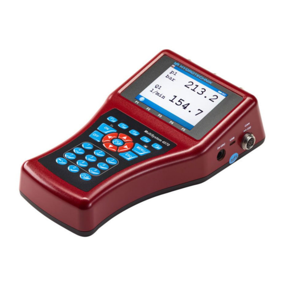
Description of the measuring instrument Description of the measuring instrument Properties of the MultiSystem 4070 The MultiSystem 4070 is a practice-oriented, user-friendly hand-held mea- suring instrument supporting the user in the daily measuring functions. When using sensors with ISDS (intelligent sensor detection), the MultiSystem 4070 automatically identifies the connected sensors during switch-on and adopts all parameters: Measurement range, physical measurand, unit of measurement, signal output and characteristic curve (linearization). -
Page 11: Connections
Description of the measuring instrument Connections Power supply – power pack Input Ch1 – analog input USB interface Digital input and output Combi jack CAN/RS232 Input Ch2 – analog input Input Ch5 – frequency input Input Ch4 – frequency/analog input Input Ch3 –... -
Page 12: Characteristics Of Analogue Inputs
Description of the measuring instrument Characteristics of analogue inputs Number 4 (Ch1 to Ch4) Signal input Switchable 0/4 … 20 mA; 0/2 … 10 V; ± 10 V; 0.5 … 4.5 V; 1 … 5 V Resolution 13-bit analogue/digital converter (12-bit + sign) Measuring rate 1.0 ms = 1 kHz... -
Page 13: Characteristics Of Frequency/Analog Inputs
Description of the measuring instrument Characteristics of frequency/analog inputs Number 1 (Ch4, Ch5) frequency/counter inputs with switchable direction detection or analog inputs Signal input 5 – 30 VDC (Frequency mode) 0.25 Hz – 20 kHz Signal input Switchable 0/4 … 20 mA; (Analog mode) 0/2 …... -
Page 14: Characteristics Of Digital Signal Input
Description of the measuring instrument Pin assignment (Analog mode) Characteristics of digital signal input Hinweis Possible damage to the instrument! This input may not be connected directly to inductive loads (e.g. coil of a magnetic valve). Otherwise the instrument may be damaged. Pins of the digital input/output (Ch6). -
Page 15: Characteristics Of Combi Jack Can / Rs 232
Description of the measuring instrument Characteristics of combi jack CAN / RS 232 8-pin M12x1 Pin assignment Function Ground Power supply for MultiXtend or CAN sensors CAN_H RTS from PC (input) CAN_L ~14.6 to 15 V, max. 800 mA (power supply) / ~ 13 VDC / 180 mA (battery) Characteristics of USB interface Micro USB Type B for communication with a PC. -
Page 16: Display
Description of the measuring instrument Display The instrument is equipped with a color display where all information and mea- sured values are displayed. Graphical presentations can be configured individually. Various items of information can be displayed as icons in the upper bar of the display: Recording bar Indicates recording in progress... -
Page 17: Keyboard
Description of the measuring instrument Keyboard The membrane keyboard is resistant to moisture and dirt; the keys are as- signed as follows: Function key 1 Function key 2 Function key 3 Function key 4 Function key 5 Switch instrument on Open Home menu... -
Page 18: Hydrocom Software Package
Description of the measuring instrument HYDROcom software package After transferring the measuring data to a PC, you can use this software to evaluate, process and present the data graphically. Technical data Casing PC+ABS+20GF plastic Weight 795 g Protection type IP40 CE conformity mark Complies with Directive 2014/30/EU (Electromagnetic Compatibility);... -
Page 19: Commissioning
Commissioning Commissioning Check delivery The measuring instrument is delivered by HYDROTECHNIK and transported by suited shipping companies. At the time of delivery to you, you should check: • Does the number of delivered items corresponds with the HYDROTECHNIK delivery note? •... -
Page 20: Charge Batteries
Commissioning Charge batteries Hinweis Battery performance endangered! Charge the instrument batteries for 3 hours before you put the instrument into opera- tion. Otherwise, there is the risk of excessive discharge, which would severely impair the battery performance. The lithium ion battery integrated in the measuring instrument will be charged as soon as the instrument is supplied by a HYDROTECHNIK power pack. -
Page 21: Operation
Operation Operation This section will provide you with all information required for the daily use of the measuring instrument. The following operations are explained: • Switch the instrument On and Off • Select operating language • Connect sensors • Enter sensor parameters •... -
Page 22: Switch The Instrument On And Off
Operation Switch the instrument On and Off Make sure that the desired sensors are connected appropriately before switching on (see section Kapitel Connect sensors auf Seite 29). If you are using ISDS sensors, the sensor parameters will be set automatically. If you use other sensors, you will have to program the sensor parameters before you can carry out measurements. -
Page 23: Operation Of The Instrument Software
Operation Operation of the instrument software After you have switched on the instrument, the Home menu or the measured values display is shown, depending on the setting in the User profile menu. If the measured values display is shown, press the key to display the Home menu. -
Page 24: Navigating In The Instrument Software
Operation Navigating in the instrument software Each icon corresponds to a menu or a dialog. There are two ways to select an icon. Highlight and ENTER Highlight the desired icon with the keys and press the key. The selected menu or dialog is displayed. Number keys You can use the number keys to select a menu quickly. -
Page 25: Favorites
Operation Navigation example Navigate to the Date/Time dialog. Menu/dialog Action Highlight and ENTER Number keys Select the Setting menu. Select the Device menu. Select the Date/Time dialog. Favorites There are three slots for favorites in the Home menu. You can assign a menu or dialog to each of the slots so that you have quick access to frequently used menus or dialogs in the Home... -
Page 26: User-Defined Softkeys
Operation User-defined softkeys You can use the F2 to F5 keys as user-defined softkeys in the measured val- ues display. Create softkeys 1 Open the Home menu: 2 Open Measure: 3 Open the favorite selection for the softkey F2: (press simultaneously) 4 Select the menu or dialog:... -
Page 27: Select Operating Language
Operation Select operating language 1 Open the Home menu: 2 Open the Setting menu: 3 Open the Device menu: 4 Open the General Settings menu: 5 Select Language with and use to open a dialog box. 6 Select the language in the dialog box: 7 Confirm changes and exit dialog: ... -
Page 28: Adjust Number Format
Operation Adjust number format You can adjust format of the numbers stored in the CSV files to the country settings 1 Open the Home menu: 2 Open the Setting menu: 3 Open the Device menu: 4 Open the General Settings menu: 5 Switch to the second page in the General Settings... -
Page 29: Set Date And Time
Operation Set date and time 1 Open the Home menu: 2 Open the Setting menu: 3 Open the Device menu: 4 Open the Date/Time dialog: 5 Enter the Date format: 6 Enter the Date: 7 Enter the Time format: 8 Enter the Time: 9 Confirm changes and exit dialog: ... -
Page 30: Enter Sensor Parameters
Operation Enter sensor parameters If you have connected ISDS sensors, the sensor parameters will be detected automatically when the instrument is switched on. Then you can skip this section. If you have connected sensors without ISDS function, you will have to program the sensor parameters manually. - Page 31 Operation Available measurands The instrument is able to process a number of different measurands including pressure, volume flow rate, temperature and rotational speed. Make sure you select the measurand and unit corresponding to the sensor. Index Measurand If several channels are programmed with the same measurand, these will be automatically indexed consecutively.
-
Page 32: Record Measuring Data
Operation Record measuring data Data are collected in measurement series. These can be configured in the cording dialog. 1 Open the Home menu: 2 Open the Setting menu: 3 Open the Recording dialog: 4 Make a selection: 5 Confirm selection: 6 Apply changes: 7 Return to the measured values display: ... -
Page 33: Delete Measuring Data
Operation Delete measuring data In the example shown, the measurement series 001, 002 and 003 have al- ready been selected for deletion, an is displayed to the left of the series. If you press , the names of the measurement files will be displayed; pressing will provide you more information about the highlighted measure- ment series. -
Page 34: Display Information On Selected File
Operation Recording time Enter how long measurement data is to be recorded. Select the desired time unit. Scanning rate Define how often measurement data is to be recorded. Select the desired time unit. Recording time and scanning rate define how often and how long measurement data is to be stored. -
Page 35: Connect A Pc And Transfer Data
Operation Connect a PC and transfer data You have to install the software HYDROcom on your PC, before you can transfer measurement data to your PC. Data transfer with micro USB cable The measuring instrument is recognized as a removable storage device. You can therefore open the operating instructions directly from the instrument. -
Page 36: Directory Structure For Data-Vol Partition
Operation Directory structure for DATA-VOL partition A directory structure has been set up on the DATA-VOL partition, the general memory for files (measurement series, images, etc.). The files are saved to dif- ferent folders by file type. You may not find all of the folders listed here in the directory structure. The folders displayed depend on the instrument version you are using. - Page 37 Operation HYDROrun Databases created with HYDROrun, e.g. measurement results of test se- quences (*.DBF). MWF files for measurement series (*.MWF). OilDiagn Measurement results from oil condition sensors. • Oil condition diagnosis file from Patrick sensor (*.OCDP) • Oil condition diagnosis file from CV100 viscosity sensor (*.OCDV) •...
-
Page 38: Reset Instrument
Operation Reset instrument All user-defined parameters and settings (channels, display, memory, etc.) will be deleted by resetting the instrument. All data on the SD card remain unaffected (measurement series, sensor and CAN database, projects, test sequences, data- bases from test sequences, etc.). 1 Switch instrument off: 2 Switch instrument on: 3 Wait until the beginning of the initialization is displayed and then press... -
Page 39: Operating Software
Operating software Operating software The operating software of the MultiSystem 4070 will be presented and ex- plained on the following pages. Frequently used functions Function in menu/dialog Keys to be used Step-by-step instructions Reset minimum/maximum value 1. Open Home: 2. Open Measure: 3. - Page 40 Operating software Function in menu/dialog Keys to be used Step-by-step instructions Quickly select a channel to enter sensor 1. Open Home: parameters 2. Open Setting: e.g. in: 3. Open Channels: 4. Open one of the following menus: • All channels •...
-
Page 41: Home
Operating software Home MENU opens the Menu; you can operate all functions of the MultiSystem 4070 from here. For the following explanations, it is assumed that the Home menu is displayed. Available menus Highlight the desired menu with and press Start recording starts the recording of measurement data;... -
Page 42: Start Recording
Operating software Start recording Start recording Confirms input/saves change. Choosing Start recording will display a dialog in which the instrument sug- gests the current time and date as the name of the measurement. The defined recording parameters (channel selection, storage duration, triggers etc.) can be set in the Recording menu. - Page 43 Operating software Mode Choose from three options: • STANDARD The defined recording and parameters will be applied to execute one sin- gle recording • CYCLIC The defined recording parameters will be applied to execute a recording; then the recording will be repeated until the key C-STOP is pressed •...
-
Page 44: Measure (Measured Values Display)
Operating software Measure (measured values display) Displays the current measured values. In the Display dialog, you can select which channels are displayed here. There are different measured values displays: • Measured values together with minimum and maximum values (MinMax) • Measured values with their units In the User profile... -
Page 45: Measured Values With Their Units
Operating software Measured values with their units Change display Change display auf Seite 44 The units are displayed to the right of each measured value. Firmware Version 1.2 MultiSystem 4070... -
Page 46: Measured Values With Minmax
Operating software Measured values with MinMax Change display Change display auf Seite 44 To the right of each measured values display, the measured minimum value (upper left) and maximum value (bottom right) are displayed. Symbols in the measured values display Channel with ISDS sensor Channel is recorded Firmware Version 1.2... -
Page 47: Error Display
Operating software Error display The following error messages may appear in the measured values display if errors occur during measurement: Error message Explanation NoCan The CAN channel is defined but the CAN bus is not enabled. CAN #1 auf Seite 89 DIV0 Division by 0 occurs when the measured value is calculated (e.g. -
Page 48: Configurations
Operating software Configurations In the Configurations menu, you can view all settings for the measuring in- strument and name and save the settings record. You can save as many configurations as you wish and then load or delete them. Save a new configuration 1 Select the Save configuration dialog:... -
Page 49: Load A Saved Configuration
Operating software Load a saved configuration 1 Select the Load configuration dialog: 2 Select a File name: 3 In the dialog box, make a selection from the list of configurations: 4 Load configuration and exit dialog: Delete a saved configuration 1 Select the Delete configuration dialog:... -
Page 50: Series Of Measurements
Operating software Series of measurements In this menu you can process, display, delete, search for and configure the presentation of recorded measurement series. Overview series Firmware Version 1.2 MultiSystem 4070... -
Page 51: Show Series
Operating software Show series DISPLAY Displays the selected measurement. INFO Displays information about the selected object. Display information on selected file auf Seite 34 Confirms input/saves change. In the Show series dialog, select a measurement series and specify the pre- sentation mode. - Page 52 Operating software Series INFO Displays information about the selected object. Display information on selected file auf Seite 34 FILE Converts the display to file name. NAME Converts the display to series name. SORT Sorts the displayed list/table. Select the measurement series 1 Open the Show series dialog:...
- Page 53 Operating software Presentation The data of the selected measurement series can be presented in four differ- ent ways: • Table: Presentation of all measured values of each channel in a table • Statistics: Presentation of the minimum, maximum and average values of each channel •...
- Page 54 Operating software Type scaling DISPLAY Displays the selected measurement. INFO Displays information about the selected object. Display information on selected file auf Seite 34 Confirms input/saves change. By default, the entire measuring range of a measurand is used as scaling. However, if you want to limit the presentation to a certain part of the measuring range, you can enable manual scaling: 1 Select...
- Page 55 Operating software Scaling Confirms input/saves change. You can set the minimal and maximal values of the measured values to be pre- sented here. • the complete measuring range (0 – 200 bar, resp. 0 – 300 l/min) is to be displayed. •...
- Page 56 Operating software Outline DISPLAY Displays the selected measurement. INFO Displays information about the selected object. Display information on selected file auf Seite 34 Confirms input/saves change. By default, measurement series are presented completely. But you may limit the range of presented values by entering a start and end time. In the example shown, only the range between 0.0 and 10.0 seconds is be shown.
- Page 57 Operating software Channels Selects all entries. Removes all selections. Confirms input/saves change. Opens the Show series (Channels) dialog. Select the channels to be presented. All channels marked with a check mark are presented. Select a channel and use to change highlighting. Press to select or deselect all channels.
- Page 58 Operating software Symbols/colors Select the symbols and colors that are to be used for the presentation of indi- vidual channels. AUTO Automatically assigns symbols and colors. Confirms input/saves change. Highlight one of the displayed channels to modify symbols and colors for it. 1 Select a channel: 2 Select the color for the channel: 3 Select a symbol for the channel:...
-
Page 59: Presentation Type "Table
Operating software Presentation type “Table” DETAIL Presentation type “Table”: Zooms into the table. RESET Presentation type “Table”: Zooms out of the table. • Independently of the recording time, a table will always contain eleven lines: • Start and end value •... -
Page 60: Presentation Type "Graph
Operating software Presentation type “Graph” ZOOM+ Activates the zoom function. ZOOM- Resets the last zoom. Positions the zoom section. SIZE Changes the zoom section. SPOT Enables the spot function. Spot function auf Seite 62 D-SPOT Enables the delta-spot function. ... - Page 61 Operating software 2 Move the inverted area: 3 Scale the inverted area: 4 Display the inverted area (apply zooming): You can use the zoom function repeatedly to show the desired area of the graph in an optimized way. 5 End graph presentation: ...
-
Page 62: Spot Function
Operating software Spot function Increment Changes the step width in the spot and delta-spot func- tions. You can use the spot function to display measured values of a certain time po- sition within the graph: 1 Enable the spot function: 2 Choose the move factor: 3 Move the spot line: 4 Read measured values. -
Page 63: Delta-Spot Function
Operating software Delta-spot function Increment Changes the step width in the spot and delta-spot func- tions. Changes the spot line that is moved with the keys. X1+X2 For the delta-spot function, two spot lines are displayed. The differences between each channel's measured values marked by the two spot lines on the curve are displayed on the right. -
Page 64: Delete Series
Operating software Delete series INFO Displays information about the selected object. Display information on selected file auf Seite 34 FILE Converts the display to file name. NAME Converts the display to series name. SORT Sorts the displayed list/table. DELETE Enables the delete function. -
Page 65: Search Series
Operating software 5 Confirm deletion with or cancel with The deletion cannot be undone. Search series SEARCH Starts the search. RESET Resets the search result. Confirms input/saves change. Use the functions of this dialog to search for recorded measurement series. 1 Open the Search series dialog:... - Page 66 Operating software 7 Sort measurement series by search result: Select Filtered. The measurement series returned by the search function are displayed at the top of the list. 8 Select the measurement series: Firmware Version 1.2 MultiSystem 4070...
-
Page 67: Setting
Operating software Setting In the Setting menu, settings can be applied for channels, display, instrument and recording. Firmware Version 1.2 MultiSystem 4070... -
Page 68: Channels
Operating software Channels FILTER Opens the Overview Filter dialog. Overview Filter auf Seite 78 There are 17 channels available: • Measurement channels; sensor connectors at the rear of the instrument • Trigger input • Trigger output • Ch17 Special channels for calculations or recording CAN signals. Press to highlight a channel. - Page 69 Operating software Configure measurement channels (Ch1 ... Ch5) Measurement channels must only be configured if you use sensors without ISDS capabilities. LOAD Loads sensor parameters from the database. SAVE Stores the current sensor parameters in the database. Confirms input/saves change. You may configure several properties for each measurement channel: Measurand Selection of measurand and unit;...
- Page 70 Operating software Channel name You may enter an individual name for each channel The name will now be shown in the tile display of the measured values display. See Tiles per page auf Seite 83. Signal type Sensor-specific The correct signal type is given on the type plate of the sensor or in its documentation.
- Page 71 Operating software Do zero point equalization After selecting the function ( ) a display will appear for confirming the zero point alignment. Press to start the zero point alignment. This process is carried out fully au- tomatically; the determined value will be displayed after a few seconds. ...
- Page 72 Operating software Using the digital signal output, you can carry out event-dependent external control. You are able to define up to 5 parameters here. Measurand shows the internal measurand of the output Channel name You can assign an arbitrary name here Mode Source of the triggering event;...
- Page 73 Operating software Configure special channels (Ch8 ... Ch17) LOAD Loads sensor parameters from the database. SAVE Stores the current sensor parameters in the database. Confirms input/saves change. The special channels are used to mathematically combine the measured val- ues of several sensors and do calculations with it, or to be configured as input channels for the CAN bus.
- Page 74 Operating software Channel name You can assign an arbitrary name here Align. Diff This function automatically determines the measured value difference be- tween the selected channels and uses it as offset. Formula Enter the desired formula here (only displayed if Calculation is set to FOR-...
- Page 75 Operating software POWER uses the formula Ch1 x Ch7 / 600 to calculate the hydraulic power The pressure p in bar is measured on channel 1 and the volume flow rate Q in l/min is measured on channel 7 FORMULA Input of an individual formula ...
- Page 76 Operating software 8 Repeat the setup for each desired channel on your MultiXtend instrument. See Connecting MultiXtend A and T auf Seite 127. Calculations with formulas LOAD Loads sensor parameters from the database. SAVE Stores the current sensor parameters in the database. Confirms input/saves change.
- Page 77 Operating software Example of a formula Ch5/600*(Ch1-Ch2) Values from special channels can only be used if the ordinal number of the used channel is lower. Possible formula on channel 14: Ch12+Ch1, impossible formula on Ch14: Ch15+Ch1. Press the key once to enter a (= channel), resp.
-
Page 78: Overview Filter
Operating software Overview Filter Press the key in the All channels dialog to display a summary of all filters. You can execute several special measurements by applying filters. Filter Choose from three digital filters: • NONE No filter applied; peak pressure measurements up to 10 kHz on channels Ch1 and Ch5 •... -
Page 79: Channel Extension
Operating software Channel extension SCAN Scans the CAN bus for messages. CREATE Compiles a list of the supported channel extension boxes. Setting Opens the dialog for settings of the highlighted mea- surement channel. LEFT Switches to next column to the left. RIGHT Switches to next column to the right. - Page 80 Operating software Selection The selected channel extension box is displayed here. You can to select a different channel extension box. Node ID Node ID of the selected channel extension box is displayed in decimal and hexadecimal numbers. Port The four possible inputs for the selected channel extension box are displayed. Additional data on the port is shown in a dedicated column under each port number.
-
Page 81: Display
Operating software Display COL/SYM Opens the Display (Symbols/colors) dialog. SCAL Opens the Scaling display dialog. Confirms input/saves change. In the Display menu, you can select which channels you would like to have displayed in the measured values display. Basic configurations are also possible. - Page 82 Operating software Presentation You can choose between the following options here: • LIST • TILES You have two possibilities for configuring the graphical presentation: • GRAPHIC y = f(t) Presentation of the channels as a function of time • GRAPHIC y = f(x) Presentation of the channels as a function of an arbitrary channel COL/SYM Opens the...
- Page 83 Operating software Tiles per page Here you have three possibilities for the tile presentation: • Shows 4 tiles in the measured values display. • Shows 9 tiles in the measured values display. • Shows 12 tiles in the measured values display. Change display ...
- Page 84 Operating software Channel on x axis Select the channel on which the function for the graphical presentation is to be based. Channels Opens the Display (channels) dialog. Select the channels to be displayed in the measured values display. All channels marked with a check mark are displayed. Select a channel and use to change highlighting.
-
Page 85: Display (Symbols/Colors) Dialog
Operating software Display (Symbols/colors) dialog AUTO Automatically assigns symbols and colors. Confirms input/saves change. First, make a selection from the Use symbols dialog entry in the Display dialog: • YES: Symbols and colors are used • NO: Only colors are used You can assign symbols and colors to the channels after making this basic selection: Open the... -
Page 86: Display Scaling Dialog
Operating software Display scaling dialog Confirms input/saves change. You have defined the measuring range of a channel in the Channels menu. See Configure measurement channels (Ch1 ... Ch5) auf Seite 69. If desired you can now define a part of the measuring range to be displayed in the graphical presentation. -
Page 87: Device
Operating software Device Configuration of the instrument is done via the Device menu. Connections Settings for CAN, COM, Lan/WLAN and, Bluetooth connections and the inter- nal USB memory General settings Settings for the language, sensors, (menu) color scheme, menu display when switching the instrument on, individual company details and softkey display, operating language Info... -
Page 88: Connections
Operating software Connections Firmware Version 1.2 MultiSystem 4070... - Page 89 Operating software CAN #1 Confirms input/saves change. Interface Enable/disable CAN bus Power supply Use this function to switch the power supply of connected CAN sensors ON and OFF. Highlight the dialog entry with and press to toggle between and OFF. Baud rate Set transmission speed for CAN data ...
- Page 90 Operating software Start CANopen Here you can trigger the start command into the CAN bus that requests the connected sensors and adaptor boxes to send data. Choose between AUTO and MANUAL. Start the request with the key. TRACE The trace function records the CAN messages. Start and stop the recording with the key.
- Page 91 Operating software The number of messages for the loaded recording is displayed in the Messag- es dialog entry. Open a loaded recording with the key. Use the keys to see the front or back of a trace line. You can use the keys to browse.
- Page 92 Operating software USB (DEVICE) Confirms input/saves change. USB mode Choose from the following options: • device: The measuring instrument is only enabled for communica- tion with the PC. Drives are not enabled for the PC. Example: using the HYDROlink software. •...
- Page 93 Operating software LAN/WLAN Confirms input/saves change. Ethernet module For the connection of the Ethernet module, connected, MultiXtend/Lan USB/WLAN can be selected. IP address Enter the IP address that the MultiSystem 4070 is to have in the Ethernet network. Port This is preassigned and displayed for information purposes only Password Enter the password for the Ethernet network, if a password is required ...
- Page 94 Operating software Bluetooth Confirms input/saves change. Select a Bluetooth module. Firmware Version 1.2 MultiSystem 4070...
-
Page 95: General Settings
Operating software General Settings Confirms input/saves change. Language You can choose from the following languages: • German • English • French • Italian • Spanish • Dutch • Danish • Bulgarian • Czech • Croatian • Hungarian • Polish • Romanian •... - Page 96 Operating software Select operating language 1 Select Language on the User profile dialog with 2 Select language: 3 Confirm changes and exit dialog: Sensor detection Adjust the instrument’s sensor detection. ISDS configuration When using ISDS sensors, the sensor parameters will be stored automatically after connecting the sensor and switching on the instrument.
- Page 97 Operating software 3 Open the Unit dialog entry: 4 Select the desired unit: 5 Confirm changes and exit dialog: The new unit system will be used the next time the instrument is switched on again. Unit Select the unit system •...
- Page 98 Operating software Company You can enter any text that will be shown in the saved logs. Enter company Confirms input/saves change. 1 In the User profile dialog, select the Company with 2 Enter text and to toggle between capital and small letters. 3 Confirm changes and exit dialog: ...
-
Page 99: Info
Operating software Softkeys Select whether softkeys are displayed as TEXT or SYMBOL. Decimal separator Select whether the decimal separator is shown as a comma or dot. List separator Select whether the list separator is shown as a semicolon or comma. System of units Choose from the following options: •... -
Page 100: Date/Time
Operating software Date/Time Confirms input/saves change. Select date format 1 In the Date/Time dialog, select the Date format with 2 Use to toggle between • DD.MM.YYYY (day.month.year) • MM/DD/YYYY (month/day/year) • YYYY.MM.DD (year.month.day) Enter date 1 In the Date/Time dialog, select the Date... -
Page 101: Memory Medium
Operating software • Enter time 1 In the Date/Time dialog, select the Time with 2 Enter hour and 3 Enter minutes and Save all changes and exit the dialog with Memory medium Hinweis Loss of data possible The internal data medium can be formatted in the Memory medium dialog. -
Page 102: Security
Operating software Format SD card When the Memory medium dialog entry is open, you can press to format the inserted SD card. This will delete all data contained on the card (e.g. mea- surement data). The formatting cannot be undone. ... -
Page 103: Calibration Setting
Operating software 9 Press to toggle between: – • The settings in the menu can be changed. • LOCKED The settings in the menu are locked and cannot be changed. When trying to apply a change in a locked menu, a corresponding warning will be dis- played after pressing 10 Confirm changes and exit dialog: ... -
Page 104: Hardware Diagnostic
Operating software Reminder If a calibration interval is exceeded, the measuring instrument displays the message Calibrate after switch-on: You can suppress the message for the selected number of days. Interval time 6, 12, 18, 24, 30 or 36 months can be set as the calibration interval. Calibrated until Displays the date up to which the calibration is valid. -
Page 105: Battery Information
Operating software Battery information Firmware Version 1.2 MultiSystem 4070... -
Page 106: Recording
Operating software Recording SETUP Opens the Setup Recording dialog. Confirms input/saves change. In the Recording dialog, you can select the channels that you would like to save in measurement series as well as the storage options. Recording time Storing time; enter time value –... -
Page 107: Trigger Function
Operating software Trigger function Confirms input/saves change. You can use the trigger function to reduce the amount of stored data by allow- ing the instrument to start the storing when the “interesting moments” are coming. Here you can define up to four triggers. Triggers are defined events that can start or stop a storing. - Page 108 Operating software Trigger mode Define the trigger: • INACTIVE The trigger is not enabled • CHANNEL Definition of a measurement channel as trigger • Triggering at the press of a key • TIMER Definition of a trigger time Definition of a measurement channel as trigger 1 For the Trigger mode, select the...
- Page 109 Operating software Trigger link Confirms input/saves change. You can link Trigger 1 with a second trigger: 1 Select the Trigger link dialog entry: 2 Select an option: • NONE: Trigger 2 is not used • AND: Trigger 1 and Trigger 2 must occur •...
- Page 110 Operating software Example of a trigger A 2-minute recording is to be started when the measured value for p2 falls be- recording low 50 bar and temperature T1 rises above 30 °C. The recording is to start 60 seconds before the trigger incident. Required programming: Recording time 2 min.
-
Page 111: Setup Recording
Operating software Setup Recording Confirms input/saves change. In the Setup Recording dialog, you can predefine settings for the recording. Recording start menu Select whether the Start recording dialog is displayed before a recording starts or whether the recording should start directly. Mode Choose from three options: •... -
Page 112: Extras
Operating software Extras Firmware Version 1.2 MultiSystem 4070... -
Page 113: Convert And Export
Operating software Convert and Export In the Convert and Exportdialog, you can convert the measurement files into CSV format. The CSV files are saved to the instrument and can then be trans- ferred to a computer. START Starts converting the selected files to CSV format. ... - Page 114 Operating software Select files INFO Displays information about the selected object. Display information on selected file auf Seite 34 FILE Only for display of measurements. Converts the display to file name. NAME Only for display of measurements. Converts the display to series name. PAGE Quick selection of a page in the dialog.
- Page 115 Operating software Color coding during file selection Individual files are color coded as follows: • Black = default • Blue = The file meets the filter criterion • = The file is faulty (e.g. a configuration file in a legacy format or a file from another measuring instrument) Firmware Version 1.2 MultiSystem 4070...
-
Page 116: Special Functions
Special functions Special functions Special functions of the instrument, which have been referred to in the previ- ous sections, are explained here. Linearization table LOAD Loads sensor parameters from the database. SAVE Stores the current sensor parameters in the database. DELETE Enables the delete function. - Page 117 Special functions The linearization table can be utilized to compensate for sensor non-lineari- ties. By calibrating a sensor, you will obtain this table, which can be entered into the measuring instrument. Five different linearization tables, each with ten value pairs, are available for each measurement channel. 1 Select the option at the Linearisation...
-
Page 118: Define Can Channel
Special functions Define CAN channel Hinweis The CAN bus must be activated in the Device menu to enable the use of a CAN channel. See chapter CAN configuration auf Seite 89 LOAD Loads sensor parameters from the database. SAVE Stores the current sensor parameters in the database. Confirms input/saves change. - Page 119 Special functions – enter a name, use to toggle between the entry of capital and small letters – – store the entered name. For the use of a MultiXtend instrument, select MultiXtend in the Calculation dia- log entry. CAN original format When entering the CAN specifications you may select the ORIGINAL format.
- Page 120 Special functions Examples Here you save all 32 bits of a multichannel. Format: ORIGINAL Bit offset: Data bits: Here you save data bits 8 to 15. Format: ORIGINAL Bit offset: Data bits: Here you save the data bits 6 to 31. If you do not want to save the “uninterest- ing”...
- Page 121 Special functions You need two special channels to display the measured values with the MultiSystem 4070. • On the first one, you define the following for the temperature sensor: Format BINARY (BIT), bit offset = 0, data bits = 8. •...
-
Page 122: Graphic Presentation In Display Menu
Special functions Graphic presentation in display menu After configuring the graphic presentation in the display menu (see Kapitel Display auf Seite 81) in the measured values display, the measured values will then look like this, for example: Change display Change display auf Seite 44 VALUE Displays the current measurement values instead of scaling. -
Page 123: Coupling Of Several Instruments
Special functions Coupling of several instruments You can couple several MultiSystem 4070 measuring instruments and in- crease the number of available input channels with almost no limitations. But please be aware that the parameters scanning rate, recording time and pre- triggers must be programmed identically at all coupled measuring instruments. -
Page 124: Serial Coupling
Special functions Serial coupling • Connect the external trigger signal to pins 3+4 [IN] of the Master instrument. • Connect the pins 1+2 [OUT] of the Master instrument with pins 3+4 [IN] of the first Slave instrument. • Connect the pins 1+2 [OUT] of the first Slave instrument with pins 3+4 [IN] of the second Slave instrument. -
Page 125: Parallel Coupling
Special functions Parallel coupling • Connect the external trigger signal to pins 3+4 [IN] of the Master instrument. • Connect the pins 1+2 [OUT] of the Master instrument with pins 3+4 [IN] of all Slave instruments. • Connect pin 2 of the Master instrument via a 2.2 kOhm resistor with pin 3 of a free measurement channel [X]. -
Page 126: Program Instruments
Special functions Program instruments Program the Master instrument 1 Program the memory channels as desired. 2 Program scanning rate, recording time and pretriggers as desired. 3 Program the storage start by a trigger (absolutely required, trigger type can be chosen freely). 4 Program the trigger output ACTIVE and set it to... -
Page 127: Transfer And Evaluate Measured Values
Special functions Transfer and evaluate measured values Transfer the measurement series from all instruments to a PC. Use the Com- bine function of the HYDROcom software to combine the measurement series. Programming and recording with HYDROlink You can simplify the coupling of instruments by using the HYDROlink software. •... -
Page 128: Enable Can Bus
Special functions Enable CAN bus Confirms input/saves change. You will have to enable the CAN bus in the CAN#1 dialog first. Hinweis Malfunctions possible! Make sure that the MultiXtend is set to the desired baud rate. Observe item 3 of the short guide. -
Page 129: Program Can Channels
Special functions Program CAN channels Observe the information in chapter Define CAN channel auf Seite 118. In the following example we show an assignment of a MultiXtend A with three sensors: • Pressure sensor 0 – 600 bar at input 1 •... -
Page 130: Start The Multixtend
Special functions Start the MultiXtend After activating the power supply, the MultiXtend must be started. Otherwise it cannot send signals. Hinweis After a loss of supply power or the measuring instrument has been switched off, the MultiXtend must be started again. 1 Open the Home menu:... -
Page 131: Viscosity-Compensated Volume Flow Rate Measurement
Special functions Viscosity-compensated volume flow rate measurement SAVE Stores the current sensor parameters in the database. Confirms input/saves change. The oil viscosity depends on its temperature. To account for these variations during the measurement of the volume flow, the following channels must be correspondingly programmed: One measurement channel for temperature (if the viscosity of the oil is not •... - Page 132 Special functions Temperature Program one measurement channel for temperature measurement. You can measurement find additional information under Kapitel Configure measurement channels (Ch1 ... Ch5) auf Seite 69. Volume flow rate Open the dialog of the measurement channel that you want to use for volume measurement flow rate measurement.
- Page 133 Special functions You can enable/disable temperature measurement in the next line. If disabled, the current viscosity cannot be calculated and the entered oil viscosity value will be used. Highlight the line Temp. meas. and press to switch it on. Highlight the next line, press and select the measurement channel, where the oil temperature is measured.
- Page 134 Special functions Selection of the oil in EDIT Edits the current entry. DELETE Enables the delete function. The database already contains several types of oil. Highlight the item Name, press and select the desired oil. To write a new oil to the database, select an empty entry (-) from the oil data- base.
- Page 135 Special functions Virtual channel for viscosity calculation LOAD Loads sensor parameters from the database. SAVE Stores the current sensor parameters in the database. Confirms input/saves change. If desired, you can program a virtual channel (see Kapitel Configure special channels (Ch8 ... Ch17) auf Seite 73) with the calculation VISCOSITY enter the required parameters.
-
Page 136: Reprogram Can Parameters
Special functions Reprogram CAN parameters SCAN Scans the CAN bus for messages. INFO Displays information about the selected object. Display information on selected file auf Seite 34 You can use the CANopen tool to reprogram the most commonly used CAN parameters provided by a CANopen instrument such as node ID or sending rate. - Page 137 Special functions Node ID Here you can see the current node IDs of the selected CANopen instrument. Possible node IDs are from 1 to 127. The node IDs are listed as decimal and hexadecimal numbers. Serial number Displays the serial number of the CANopen instrument as decimal and hexa- decimal numbers.
- Page 138 Special functions • The TPDO address is defined by the DIP switch. • Firmware+DIP The TPDO address is not defined by the DIP switch/firmware combination. It may not be possible to adjust individual parameters on all CANopen instru- ments. If this is the case, the error message “Function not supported” or “Product code not supported”...
-
Page 139: Icon Reference
Icon reference Icon reference The operating software uses icons. Favorites You can assign the following icons as favorites in the Home menu or as soft- keys in the measured values display. Favorites auf Seite 25 Favorite Overview Series of measurements >... - Page 140 Icon reference Load Special applications > Load valve valve Special applications auf Seite 149 Patrick Special applications > Patrick Special applications auf Seite 149 Measuring section Special applications > Meas. section CX197 CX197 Special applications auf Seite 149 Test sequences Special applications >...
- Page 141 Icon reference Channel extension Settings > Channels > Channel extension Channel extension auf Seite 79 Date/Time Settings > Device > Date/Time Set date and time auf Seite 29 Date/Time auf Seite 100 User Settings > Device > General Settings profile ...
- Page 142 Icon reference Convert and Export Extras > Convert and Export Convert and Export auf Seite 113 CANopen Tool Extras > CANopen Tool Reprogram CAN parameters auf Seite 136 HOLD Only permissible as softkey. “Freezes” the measured values display. Firmware Version 1.2 MultiSystem 4070...
-
Page 143: Softkeys: Symbols/Text
Icon reference Softkeys: Symbols/text In the User profile dialog, select whether softkeys are displayed in the dialogs as symbols or text. See User-defined softkeys auf Seite 26. DETAIL Presentation type “Table”: Zooms into the table. RESET Presentation type “Table”: Zooms out of the table. ZOOM+ Presentation type “Graph”: Activates the zoom func- tion. - Page 144 Icon reference Toggle function: Switches to UPPER CASE. Toggle function: Switches to lower case. POS1 Positions the cursor at the start of the entry. Positions the cursor at the end of the entry. LEFT Switches to next column to the left. RIGHT Switches to next column to the right.
- Page 145 Icon reference Selects all entries. Removes all selections. COL/SYM Opens the Display (Symbols/colors) dialog. NOTE Adds a note. FORMAT Formats the selected volume. FILE Converts the display to file name. NAME Converts the display to series name. SORT Sorts the displayed list/table. >>...
- Page 146 Icon reference SETUP/Setting • Opens the Setup Recording dialog. • Opens the dialog for setting the highlighted channel. SEARCH Starts the search. RESET Resets the search result. LOAD Loads data, e.g. sensor parameters. SAVE Saves data, e.g. sensor parameters. SELECT Opens the editing function.
-
Page 147: Cleaning And Maintenance
Cleaning and maintenance Cleaning and maintenance Cleaning Vorsicht Damage to the instrument is possible! Switch the instrument off and disconnect from the power supply BEFORE starting to clean. This prevents the risk of a short-circuit, and thereby possible damage to the instrument. -
Page 148: Repair
Cleaning and maintenance Repair If repair is needed, please contact our customer service department. Please have the following information ready when you contact us. If you are returning the instrument, please also attach the following information: • Company, department, contact person •... - Page 149 Special applications Special applications This submenu contains several functions which enhance the functionality of the MS 4070 or which are required for the operation of external devices. There is a detailed description of the menus in a separate document. Firmware Version 1.2 MultiSystem 4070...
Need help?
Do you have a question about the HYDROTECHNIK MultiSystem 4070 and is the answer not in the manual?
Questions and answers