Table of Contents
Advertisement
Quick Links
User manual IM3
Pt1000 2-wire -200.0°C...850.0°C / -328.0°F...1562.0°F
Technical features:
• red display of -19999...99999 digits (optional: green, orange or blue display)
• minimal installation depth: 90 mm without plug-in screw terminal
• min/max-memory
• display flashing at threshold value exceedance / threshold value undercut
• permanent min/max-value recording
• brightness control
• programming interlock via access code
• protection class IP65 at the front side
• plug-in screw terminal
• optional: 2 PhotoMos outputs
• optional: sensor supply or analog output
• accessories: PC-based configuration-kit PM-TOOL with CD & USB-adapter for
devices without keypad and for a simple adjustment of standard devices
Advertisement
Table of Contents

Subscribe to Our Youtube Channel
Related Manuals for ICS Pt1000


Summary of Contents for ICS Pt1000
- Page 1 User manual IM3 Pt1000 2-wire -200.0°C…850.0°C / -328.0°F…1562.0°F Technical features: • red display of -19999…99999 digits (optional: green, orange or blue display) • minimal installation depth: 90 mm without plug-in screw terminal • min/max-memory • display flashing at threshold value exceedance / threshold value undercut •...
- Page 2 Green Supply voltage Orange 7 24 VDC galv. isolated S 85-265 VAC Number of digits 5-digit Measuring input C Pt1000 up to 850°C Digit height Analog output 10 mm 0 without Digital input X 0-10 VDC, 0/4-20 mA without Temperature devices 6 Pt1000 2-wire Please state physical unit by order, e.g °C...
-
Page 3: Table Of Contents
Contents 1. Brief description 2. Assembly 3. Electrical connection 4. Functions and operation description 4.1. Programming software PM-TOOL 5. Setting up the device 5.1. Switching on 5.2. Standard parameterisation (flat operation level) Value assigment for triggering of the signal input 5.3. -
Page 4: Brief Description
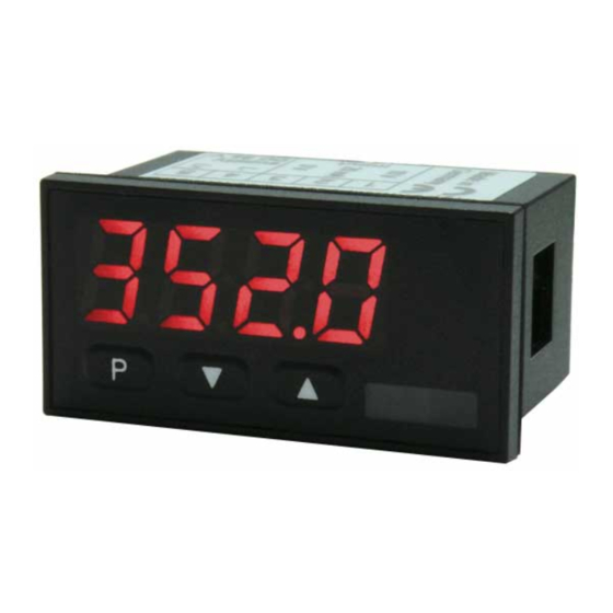
1. Brief description 1. Brief description The panel meter IM3-7C6 is a 5-digit device for Pt1000 temperature sensor and a visual threshold value monitoring via the display. The configuration happens via three front keys or via the optional PC software PM-TOOL. An integrated programming interlock prevents unrequested changes of the parameters and can be unlocked again by an individual code. -
Page 5: Assembly
2. Assembly 2. Assembly Please read the Safety advices on page 25 before installation and keep this user manual for future reference. Gap for physical dimension 1. After removing the fixing elements, insert the device. 2. Check the seal to make sure it fits securely. 3. -
Page 6: Electrical Connection
3. Electrical connection 3. Electrical connection Type IM3-7VT5A.060C.S70xD supply of 100-240 VAC Type IM3-7VT5A.060C.770xD supply of 24 VDC... -
Page 7: Functions And Operation Description
4. Function and operation description 4. Function and operation description Operation The operation is divided into three different levels. Menu level (delivery status) The menu level is for the standard settings of the device. Only menu items which are sufficient to set the device into operation are displayed. To get into the professional level, run through the menu level and parameterise prof under menu item RUN. - Page 8 4. Function and operation description Function chart: 4.1 Parameterisation software PM-TOOL: Included in the delivery of the PM-TOOL are the software on CD and an USB-cable with device adapter. The connection happens via a 4-pole micromatch-plug on the back side of the device, to the PC-side the connection happens via an USB plug.
-
Page 9: Setting Up The Device
5. Setting up the device 5. Setting up the device 5.1. Switching on Once the installation is complete, start the device by applying the voltage supply. Before, check once again that all electrical connections are correct. Starting sequence For 1 second during the switching-on process, the segment test (8 8 8 8 8) is displayed followed by an indication of the software type and, after that, also for 1 second the software version. - Page 10 5. Setting up the device Menu level Parameterisation level Setting the display time, Default: then The display time is set with [▲] [▼]. The display moves up in increments of 0.1 up to 1 second and in increments of 1.0 to 10.0 seconds. Confirm the selection by pressing the [P] button.
- Page 11 5. Setting up the device Menu level Parameterisation level Hysteresis for limit values, Default: The delayed reaction of the alarm is the difference to the threshold value, which is defined by the hysteresis. Function for threshold value undercut / exceedance, Default: A limit value undercut is selected with (for LOW = lower limit value), a limit...
-
Page 12: Programming Interlock Run
5. Setting up the device Menu level Parameterisation level User code (4-digit number-combination, free available), Default: If this code was set (>0000), all parameters are locked for the user, if been selected before under menu item . By pressing [P] for 3 seconds in operation mode, the display shows . -
Page 13: Extended Parameterisation (Professional Operation Level)
5. Setting up the device 5.4. Extended parameterisation (Professional operation level) 5.4.1. Signal input parameters Menu group level Menu level Menu level Parameterisation level Type of temperature metering, Default: The temperature can be displayed in °C or in °F. Confirm the selection with [P] and the display switches back to menu level. - Page 14 5. Setting up the device Menu level Parameterisation level Setting the display time, Default: then The display time is set with [▲] [▼]. The display moves up in increments of 0.1 up to 1 second and in increments of 1.0 to 10.0 seconds. Confirm the selection by pressing the [P] button.
-
Page 15: General Device Parameter Fct
5. Setting up the device 5.4.2. General device parameters Menu group level Menu level Menu level Parameterisation level Display time, Default: then The display is set up with [▲] [▼]. Thereby it switches until 1 second in increments of 0.1 seconds and until 10.0 seconds in increments of 1.0. With [P] the selection is confirmed and the device changes into menu level. - Page 16 5. Setting up the device Menu level Parameterisation level Display flashing, Default: A display flashing can be added as additional alarm function either to single or to a combination of off-limit condition. With , no flashing is allocated. Assignment (deposit) of key functions, Default: For the operation mode, special functions can be deposited on the navigation keys [▲] [▼], in particular this function is made for devices in housing size...
-
Page 17: Safety Parameter Cod
5. Setting up the device 5.4.3. Safety parameters Menu group level Menu level Menu level Parameterisation level User code Default: Via this code, reduced sets of parameters can be released. A change of the can be done via the correct input of the (master code). -
Page 18: Analog Output Parameter Out
5. Setting up the device Menu level Parameterisation level Release/lock alarm parameters, Default: This parameter describes the user release/user lock of the alarm: : here only the range of value of the threshold values 1-4 can be changed : here the range of value and the alarm trigger can be changed all alarm parameters are released all alarm parameters are locked Back to menu group level,... - Page 19 5. Setting up the device Menu level Parameterisation level Setting up the final value of the analog output, Default: The final value can be adjusted from the smallest to the largest digit with [▲] [▼]. Confirm each digit with [P]. A minus sign can only be parameterized on the leftmost digit.
-
Page 20: Relay Functions Rel
5. Setting up the device 5.4.5. Relay functions Menu group level Menu level Menu level Parameterization level Alarm relay 1, Default: …. …. Each setpoint (optional) can be linked up via 4 alarms (by default). This can either be inserted at activated alarms or deactivated alarms . - Page 21 5. Setting up the device Menu level Parameterization level Alarms for relay 1, Default: …. The allocation of the alarms to relay 1 happens via this parameter, one alarm or a group of alarms can be chosen. With [P] the selection is confirmed and the device changes into menu level.
-
Page 22: Alarm Parameter Al1
5. Setting up the device Menu level Parameterization level Alarms for relay 2, Default: …. The allocation of the alarms to relay 5 happens via this parameter, one alarm or a group of alarms can be chosen. With [P] the selection is confirmed and the device changes into menu level. - Page 23 5. Setting up the device Menu level Parameterization level Hysteresis for threshold values, Default: The delayed reaction of the alarm is the difference to the threshold value, which is defined by the hysteresis. Function for threshold value undercut / exceedance, Default: A limit value undercut is selected with (for LOW = lower limit value), a limit...
-
Page 24: Reset To Factory Settings
6. Reset to factory settings Programming interlock, Menu group level Description see page 10, menu level 6. Reset to factory settings To return the unit to a defined basic state, a reset can be carried out to the default values. The following procedure should be used: •... -
Page 25: Alarms / Relays
7. Alarms / Relays 7. Alarms / Relays This device has 4 virtual alarms that can monitor one limit value in regard of an undercut or exceedance. Each alarm can be allocated to an optional relay output S1-S2; furthermore alarms can be controlled by events like e.g. min/max-value. Function principle of alarms / relays Alarm / Relay x Deactivated, instantaneous value, min/max-value... - Page 26 7. Alarms / Relays Quiescent current By quiescent current the alarm S1-S2 is on below the threshold and switched off on reaching the threshold. Switching-on delay The switching-on delay is activated via an alarm and e.g. switched 10 seconds after reaching the switching threshold, a short-term exceedance of the switching value does not cause an alarm, respectively does not cause a switching operation of the relay.
-
Page 27: Technical Data
Underflow horizontal bars at the bottom Display time 0.1 to 10.0 seconds Input Measuring range Measuring error Digit Pt1000 2-wire -200°C…850.0°C 0.1 % of measuring range ±1 Accuracy Temperature drift 100 ppm / K Measuring time 0.1…10.0 seconds... - Page 28 8. Technical data Ambient conditions Working temperature 0…50°C Storing temperature -20…80°C Weathering resistance 0-80% relative humidity on years average without dew EN 61326 CE-sign Conformity according to directive 2014/30/EU Safety standard according to low voltage directive 2014/35/EU EN 61010; EN 60664-1...
-
Page 29: Safety Advices
9. Safety advices 9. Safety advices Please read the following safety advices and the assembly in chapter 2 before installation and keep it for future reference. Proper use The IM3-7C6-device is designed for the evaluation and display of sensor signals. Danger! Careless use or improper operation can result in personal injury and/or can damage the equipment. -
Page 30: Error Elimination
10. Error elimination 10. Error elimination Error description Measures The unit permanently indicates • The input has a very high measurement, overflow. check the measuring circuit. • The input is open. The unit permanently shows • The input has a very low measurement, underflow.
Need help?
Do you have a question about the Pt1000 and is the answer not in the manual?
Questions and answers