Table of Contents
Advertisement
Quick Links
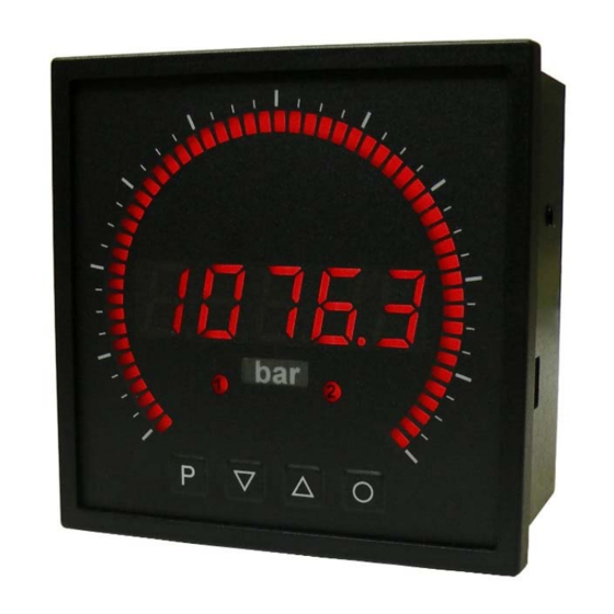
User manual IMB2-2F
Frequency input: 0.01 Hz up 999.99 kHz
Connection for NAMUR-, NPN-, PNP- and TTL-sensors
Technical features:
• red display of -19999...99999 digits
• red 55 points bargraph
• adjustable bar or dot operation or operation with permanent display of center point
• min/max memory
• display adjustment via frequency presetting or directly on the sensor signal
• 30 adjustable setpoints
• display flashing at threshold value exceedance/undercut
• Schmitt-Trigger-input
• zero-key for triggering of Hold, Tara
• permanent min/max-value recording
• digital frequency filter for contact bounce suppression and interference suppresion
• frequency filter with varying pulse control factor
• volume metering (totaliser) for frequencies up to 1kHz (accurate to a pulse)
• mathematical function like reciprocal value, square root, rounding
• sliding averaging with an optional dynamic display filter
• setpoint generator
• brightness control
• programming interlock via access code
• protection class IP65 at the front side
• plug-in screw terminal
• sensor supply
• galvanic isolated digital input
• 2 relay output
• optional analog output
• optional: RS232 or RS485 interfaces
• accessories: PC-based configuration-kit PM-TOOL incl. CD & USB adapter for devices
without keypad and for a simple adjustment of standard devices.
Advertisement
Table of Contents

Related Manuals for ICS IMB2-2F


Summary of Contents for ICS IMB2-2F
- Page 1 User manual IMB2-2F Frequency input: 0.01 Hz up 999.99 kHz Connection for NAMUR-, NPN-, PNP- and TTL-sensors Technical features: • red display of -19999…99999 digits • red 55 points bargraph • adjustable bar or dot operation or operation with permanent display of center point •...
- Page 2 Identification STANDARD TYPES ORDER NUMBER IMB2-2FR5RR.0307.S72AD Frequency IMB2-2FR5RR.0307.W72AD Housing size: 96x96 mm Options – breakdown of order code: I M B 2- 2 F R 5 R R. 0 3 0 7. W 7 2 A Standard type M-Line Dimension physical unit Bargraph Version...
-
Page 3: Table Of Contents
Contents Brief description Assembly Electrical connection Description of function and operation 4.1. Programming software PM-TOOL Seting up the device 5.1. Switching on 5.2. Standard parameterisation (flat operation level) Value assignment for the triggering of the signal input of the digital display and bargraph display 5.3. -
Page 4: Brief Description
1. Brief description 1. Brief description The panel meter instrument IMB2-2F is a 5-digit digital display with a 55 points bargraph display and two galvanic isolated setpoints; designed for pulse signals respectively 2- and 3-wire sensors. The configuration happens via four keys at the front. The integrated programming interlock prevents unrequested changes of parameters and can be unlocked again with an individual code. -
Page 5: Assembly
2. Assembly 2. Assembly Please read the Safety advices on page 37 before installation and keep this user manual for future reference. After removing the fixing elements, insert the device. Check the seal to make sure it fits securely. Click the fixing elements back into place and tighten the clamping screws by hand. Then use a screwdriver to tighten them another half a turn. -
Page 6: Electrical Connection
3. Electrical connection 3. Electrical connection Attention! For devices with sensor supply, terminal clamps 4 and 18, aswell as 3 and 19 are connected galvanically in the device. - Page 7 3. Electrical connection IMB2-2F-devices with a frequency input / pulse input...
-
Page 8: Description Of Function And Operation
4. Description of function and operation 4. Description of function and operation Operation The operation is divided into three different levels. Menu level (delivery status) This level was designed for the standard settings of the device. Only menu items which are sufficent to set the device into operation are displayed. - Page 9 4. Description of functions and operation Funktion chart: 4.1 Parameterisation software PM-TOOL: Part of the PM-TOOL are the software on CD and an USB-cable with device adapter. The connection happens via a 4-pole micromatch-plug on the back side of the device, to the PC-side the connection happens via an USB plug.
-
Page 10: Programming Software Pm-Tool
5. Setting up the device 5. Setting up the device 5.1. Switching-on Once the installation is complete, start the device by applying the voltage supply. Before, check once again that all electrical connections are correct. Starting sequence For 1 second during the switching-on process, the segment test (8 8 8 8 8) is displayed, followed by an indication of the software type and, after that, also for 1 second, the software version. - Page 11 5. Setting up the device Menu level Parameterisation level Setting the start/offset value of the measuring range, offs: Default: 0 Enter the start/offset value from the smallest to the highest digit [▲] [▼] and confirm each digit with [P]. After the last digit the display switches back to the menu level. If Sens.F was selected as the input option, you can only select between noca and cal.
- Page 12 5. Setting up the device Menu level Parameterisation level Setting of the pulse delay, dELAY: Default: 0 With the pulse delay of 0–250 seconds (max), frequencies can be collected, which are even smaller than by the predetermined measuring time of the device. If e.g. a delay of 250 seconds is set, it means that the device waits up to 250 seconds for an edge, before it assumes a 0 Hz frequency.
- Page 13 5. Setting up the device Menü-Ebene Parameter-Ebene Selection of analog output, Out.rA: Default: 4-20 Three output signals are available: 0-10 VDC, 0-20 mA and 4-20 mA, with this function, the demanded signal is selected. Setting up the final value of the analog output, Out.En: Default: 10000 The final value is adjusted from the smallest digit to the highest digit with [▲] [▼] and digit by digit confirmed with [P].
- Page 14 5. Setting up the device Menu level Parameterisation level Function if display falls below / exceeds limit value, FU-1: Default: high The limit value undercut can be selected with Louu (LOW = lower limit value) and limit value exceedance can be selected with high (HIGH = upper limit value). If e.g. limit value 1 is on a switching threshold of 100 and occupied with function „high“, the alarm will be activated by reaching the threshold.
-
Page 15: Programming Interlock „Run
5. Setting up the device Menu level Parameterisation level Master code (4-digit number-combination free available), A.CodE: Default: 1234 This code can unlock all parameters, if LOC has been activated before under menu item run. By pushing [P] during operation mode for approx. 3 seconds, Code appears in the display. The user can now reach all parameters by entering A.codE. -
Page 16: Extended Parameterisation (Professional Operation Level)
5. Setting up the device 5.4. Extended parameterisation (Professional operation level) 5.4.1. Signal input parameters Menu group level Menu level Menu level Parameterisation level Selection of the input signal, tYPE: Default: fre9u If the scaling of the device is done via SEnS.F (Sensor calibration), the frequency range needs to be preset under rAnGE and is adjusted by application of the final value/initial value. - Page 17 5. Setting up the device Menu level Parameterisation level Setting the start/offset value of the measuring range, offs: Default: 0 Enter the start/offset value from the smallest to the highest digit [▲] [▼] and confirm each digit with [P]. After the last digit the display switches back to the menu level. If Sens.F was selected as the input option, you can only select between noca and cal.
- Page 18 5. Setting up the device Menu level Parameterisation level Setting of the pulse delay, dELAY: Default: 0 With the impulse delay of 0–250 seconds (max), frequencies can be collected, that are even smaller than by the predetermined measuring time of the device. If e.g. a delay of 250 seconds is set, this means that the device waits up to 250 seconds for an edge, before it assumes a 0 Hz frequency.
- Page 19 5. Setting up the device Menu level Parameterisation level Display values for setpoints, dIS.01 … dIS.30: Under this parameter setpoints are defined according to their value. At the sensor calibration, like at final value/offset, one is asked at the end if a calibration shall be activated. Analog values for setpoints, InP.01 …...
-
Page 20: General Device Parameters „Fct
5. Setting up the device 5.4.2. General device parameters Menu group level Menu level Menu level Parameterisation level Display time, DISEC: Default: 01.0 then The display is set up with [▲] [▼]. Thereby you switch until 1 second in 0.1 steps and until 10.0 seconds in 1.0-steps. - Page 21 5. Setting up the device Menu level Parameterisation level Dynamic for the sliding average determination, step: Default: no With step the sliding average determination can be adjusted dynamically. If 6pro or 12pro was selected, a frequency value with a variance of 6% or 12% of the current display value is taken over directly for the sliding averaging.
- Page 22 5. Setting up the device Menu level Parameterisation level Display, dISPL: Default: Actua With this function the current measuring value, min/max value, totaliser value, the process- controlled hold value, the sliding average value, the constant value or the difference between the constant value and the current value can be allocated to the display.
- Page 23 5. Setting up the device Menu level Parameterisation level Assignment (deposit) of key functions, tASt: Default: no For the operation mode, special functions can be deposited on the navigation keys [▲] [▼]. In particular this function is made for devices in housing size 48x24mm which do not have a 4th key ([O]-key).
- Page 24 5. Setting up the device Menu level Parameterisation level Special function [O]-key, tASt.4: Default: no … For the operation mode, special functions can be deposited on the [O]-key. This function is activated by pressing the key. With tArA the device is set temporarily on a parameterised value. The device acknowledges the correct taring with showing oo0oo in the display.
-
Page 25: Bargraph Functions „Bar
5. Setting up the device 5.4.3. Bargraph functions Menu group level Menu level Menu level Parameterisation level Bargraph, Ba.src: Default: actua With this function the following values can be allocated to the display: the current measurand, the min/max value, the totaliser value, the process-controlled hold value, the sliding average value, the constant value or the difference between constant and current value of the bargraph. - Page 26 5. Setting up the device Menu level Parameterisation level Bargraph alerting, ba.l1m: Default: no During a breach of the alarms (AL1 to Al4), a flashing of the dots can be allocated to the bargraph by selecting Flash. If No is adjusted, the bargraph remains statical. With [P] the selection is confirmed and the device changes into menu level.
-
Page 27: Safety Parameters „Cod
5. Setting up the device 5.4.4. Safety parameters Menu group level Menu level Menu level Parameterisation level Setting up the user code, U.Code: Default: 0000 Via this code, reduced sets of parameters out.le and al.lev can be unlocked, in case of a locked programming. -
Page 28: Serial Parameters „Ser
5. Setting up the device Menu level Parameterisation level Back to menu group level, rEt: With [P] the selection is confirmed and the device changes into menu group level „–COD–“. 5.4.5. Serial parameters Menu group level Menu level Menu level Parameterisation level Device address, ADDR: Default: 001... -
Page 29: Analog Output Parameters „Out
5. Setting up the device 5.4.6. Analog output parameters Menu group level Menu level Menu level Parameterisation level Selection reference of analog output, OutPt: Default: actua The analog output signal can refer to different functions, in detail these are the current measurand, the min-value, the max-value, the totaliser function/sum function, the constant value or the difference between current measurand and constant value. - Page 30 5. Setting up the device Menu level Parameterisation level Overflow behaviour, O.FLoU: Default: edge To recognise and evaluate faulty signals, e.g. by a controller, the overflow behaviour of the analog output can be defined. As overflow can be seen either EdGE, that means the analog output runs on the set limits e.g.
-
Page 31: Relay Functions „Rel
5. Setting up the device 5.4.7. Relay functions Menu group level Menu level Menu level Parameterisation level Alarm relay 1, rEL-1: Default: al-1 …. …. Each setpoint (optional) can be linked up via 4 alarms (by default). This can either be inserted at activated alarms Al-1/4 or deactivated alarms Aln1/4. - Page 32 5. Setting up the device Menu level Parameterisation level Alarm relay 2, rEL-2: Default: al-2 …. …. Each setpoint (optional) can be linked up via 4 alarms (by default). This can either be inserted at activated alarms Al-1/4 or deactivated alarms Aln1/4. If LOGIC was selected, logical links are available in the menu level Log-1 and Com-1.
-
Page 33: Alarm Parameters „Al1
5. Setting up the device 5.4.8. Alarm parameters Menu group level Menu level Menu level Parameterisation level Dependency alarm 1, ALrM.1: Default: actua The dependency of alarm 1 can be related to special functions, in detail these are the current measuring value, the min-value, the max-value, the totaliser value/sum-value, the constant value or the difference between the current measurand and the constant value. - Page 34 5. Setting up the device Menu level Parameterisation level Function for threshold value undercut/exceedance, Fu-1: Default: high A limit value undercut is selected with Louu (for LOW = lower limit value), a limit value exceedance with High (for HIGH = higher limit value). If e.g. limit value 1 is on a threshold level of 100 and allocated with function High, an alarm is activated by reaching the threshold level.
-
Page 35: Totaliser (Volume Metering) „Tot
5. Setting up the device 5.4.9. Totaliser (Volume metering) Menu group level Menu level Menu level Parameterisation level Totaliser state, total: Default: off The totaliser makes measurements on a time base of e.g. l/h possible, at this the scaled input signal is integrated by a time and steadily (select Stead) or temporarily (select temp) saved. - Page 36 6. Reset to default values Menu level Parameterisation level Totaliser reset, tot.re: Default: 000 The reset value is adjusted from the smallest to the highest digit with the navigation keys [▲] [▼] and digit per digit confirmed with [P]. After the last digit, the display switches back to the menu level.
-
Page 37: Alarms / Relay
7. Alarms / Relays 7. Alarms / Relays This device has 4 virtual alarms that can monitor one limit value in regard of an undercut or exceedance. Each alarm can be allocated to an optional relay output S1-S2; furthermore alarms can be controlled by events like e.g. -
Page 38: Interfaces
8. Interfaces 8. Interfaces The interface RS485 is connected via a screened data line with twisted wires (Twisted-Pair). On each end of the bus segment a termination of the bus lines needs to be connected. This is neccessary to ensure a secure data transfer to the bus. For this a resistance (120 Ohm) is interposed between the lines Data B (+) and Data A (–). -
Page 39: Programming Examples
9. Programmer examples 9. Programmer examples Examples: Adjustment according to number of sprockets at unknown rotation speed. - nearly 100% of the rotation speeds are in the range of 0 to 30.000 r.p.m. - the number of sprockets varies (without gearing) between 1 and 100 - in automation, the frequency supply never exceeds 10 kHz (rather 3 kHz) Assume a rotation speed of 60 r.p.m. -
Page 40: Rotational Speed
9. Programmer examples Example: Rotation speed of a machine shaft There are 4 sprockets on one machine shaft. Applied in an angle of 90° to each other and to the rotation speed measurement. The sprockets are collected via a proximity switch and evaluated by the frequency device, which shall display the rotation speed in U/min. -
Page 41: Technical Data
10. Technical data 10. Technical data Panel meter housing Dimensions 96x96x56 mm (BxHxD) 96x96x82 mm (BxHxD) incl. plug-in terminal +0.6 +0.6 Panel cut-out 91.0 x 91.0 Wall thickness up to 10 mm Fixing Screw elements Material LEXAN 500R, black Sealing material EPDM, 65 Shore, black Protection class Standard IP65 (front), IP00 (back side) - Page 42 10. Technical data Output Sensor supply 24 VDC / 50 mA; 12 VDC / 50 mA; 5 VDC / 20 mA 0/4-20 mA / burden 350 Ω or 0-10 VDC / 10 kOhm, 16 bit Analog output Switching output Relay with change-over 250 VAC / 5 AAC;...
-
Page 43: Safety Advices
Please inform the supplier immediately of any damage. Installation The IMB2-2F-device must be installed by a suitably qualified specialist (e.g. with a qualification in industrial electronics). Notes on installation • There must be no magnetic or electric fields in the vicinity of the device, e.g. due to transformers, mobile phones or electrostatic discharge. -
Page 44: Error Elimination
12. Error elimination 12. Error elimination Measures Error description • The input frequency is too high for the selected frequency range. Correct range The device shows a permanent overflow according to this. • Disturbing pulses lead to an increased input frequency, activate fi.frq at smaller frequencies or shield the senor line.
Need help?
Do you have a question about the IMB2-2F and is the answer not in the manual?
Questions and answers