Table of Contents
Advertisement
Quick Links
Parrilla a Gas de 6 Quemadores
OWNER'S MANUAL / MANUAL DEL PROPIETARIO
GUARDE ESTE MANUAL PARA REFERENCIA FUTURA
NOTICE TO INSTALLER:
LEAVE THESE INSTRUCTIONS
WITH THE GRILL OWNER FOR
FUTURE REFERENCE .
AVISO PARA EL
INSTALADOR:
ENTREGUE ESTAS
INSTRUCCIONES AL
PROPIETARIO DE LA PARRILLA
PARA REFERENCIA FUTURA.
6 Burner Gas Grill
ASSEMBLY AND OPERATING IN STRUC TIONS
INSTRUCCIONES DE ARMADO Y OPERACIÓN
SAVE THIS MANUAL FOR FUTURE REFERENCE
MODEL / MODELO 810-6640-S
HAZARDOUS EXPLOSION MAY RESULT IF THESE WARNINGS AND INSTRUCTIONS
ARE IGNORED. READ AND FOLLOW ALL WARNINGS AND INSTRUCTIONS IN THIS
SE PUEDE PRODUCIR UNA EXPLOSIÓN PELIGROSA SI SE HACE CASO OMISO A
ESTAS ADVERTENCIAS E INSTRUCCIONES. LEA Y SIGA TODAS LAS ADVERTENCIAS
E INSTRUCCIONES EN ESTE MANUAL PARA EVITAR LESIONES PERSONALES,
WARNING/ADVERTENCIA
MANUAL TO AVOID PERSONAL INJURY, INCLUDING DEATH OR
PROPERTY DAMAGE.
INCLUSO LA MUERTE, O LOS DA—OS MATERIALES.
FPO
Advertisement
Chapters
Table of Contents

Related Manuals for Brinkmann 810-6640-S


Summary of Contents for Brinkmann 810-6640-S
- Page 1 ASSEMBLY AND OPERATING IN STRUC TIONS INSTRUCCIONES DE ARMADO Y OPERACIÓN SAVE THIS MANUAL FOR FUTURE REFERENCE GUARDE ESTE MANUAL PARA REFERENCIA FUTURA MODEL / MODELO 810-6640-S WARNING/ADVERTENCIA NOTICE TO INSTALLER: HAZARDOUS EXPLOSION MAY RESULT IF THESE WARNINGS AND INSTRUCTIONS LEAVE THESE INSTRUCTIONS ARE IGNORED.
- Page 2 IMPORTANT SAFETY WARNINGS WE WANT YOU TO ASSEMBLE AND USE YOUR GRILL AS SAFELY AS POSSIBLE. THE PURPOSE OF THIS SAFETY ALERT SYMBOL IS TO ATTRACT YOUR ATTEN- TION TO POSSIBLE HAZARDS AS YOU ASSEMBLE AND USE YOUR GRILL. WHEN YOU SEE THE SAFETY ALERT SYMBOL PAY CLOSE ATTENTION TO THE INFORMATION WHICH FOLLOWS! READ ALL SAFETY WARNINGS AND INSTRUCTIONS CAREFULLY BEFORE ASSEMBLING AND OPERATING YOUR GRILL.
-
Page 3: Table Of Contents
TABLE OF CONTENTS: General Warnings ..........3-4 LP Gas Cylinder (Tank) Specifi cations and Installation . -
Page 4: General Warnings
GENERAL WARNINGS: WARNING • Leak test all connections before fi rst use, even if grill was purchased fully assembled and after each tank refi ll. Check the propane tank rubber seal for damage. • Always check the grill and propane tank prior to each use as indicated in the “Checking for Leaks”... -
Page 5: Lp Gas Cylinder (Tank) Specifications And Installation
• Grill is hot when in use. To avoid burns: • DO NOT attempt to move the grill. • Block the wheels so the unit does not accidentally move. • Wear protective gloves or oven mitts. • DO NOT touch any hot grill surfaces. •... - Page 6 LP GAS CYLINDER (TANK) SPECIFICATIONS: LP gas cylinder (not supplied with this grill) The LP (Liquid Propane) gas cylinder specifi cally designed to be used with this grill must be 12” (30.5 cm) diameter x 18” (45.7 cm) tall and have a 20 lb. (9.1 kg) capacity incorporating a Type 1 cylinder valve and an over-fi lling protection device (OPD).
-
Page 7: Hose & Regulator Specifications And Installation
• DO NOT attempt to connect grill, as purchased for LP (propane) gas, to any other fuel supply source such as a natural gas line. A Brinkmann conversion kit must be purchased and installed for use with natural gas. •... -
Page 8: Leak Testing
HOSE AND REGULATOR: Your grill is equipped with a Type 1 connection device with the following features: 1. The system will not allow gas fl ow from the cylinder until a positive connection to the valve has been made. Note: The cylinder valve and all grill burner knobs must be turned OFF before any connection is made or removed. - Page 9 DANGER To prevent fi re or explosion hazard: • DO NOT smoke or permit ignition sources in the area while conducting a leak test. • Perform test OUTDOORS in a well ventilated area that is protected from the wind. • Never perform a leak test with a match or open fl ame.
-
Page 10: Pre-Start Check List
PRE-START CHECK LIST: DANGER Property damage, bodily harm, severe burns, and death could result from failure to follow these safety steps. These steps should be performed after the grill has been assembled and prior to each use. DO NOT operate this grill until you have read and understand ALL of the warnings and instructions in this manual. - Page 11 6. If burner does not ignite using the igniter, see “Match Lighting the Main Burners” section. 7. To turn off, turn each control knob clockwise until it locks in the “OFF” position. This does not turn off the gas flow from the cylinder. Note: If burner does not light or flame is too low, See “Trouble Shooting”...
-
Page 12: Operating The Grill
OPERATING THE GRILL: WARNING • Read and follow all warnings and instructions contained in the preceding sections of this manual. • Never use charcoal, lava rocks or wood briquets in a gas grill. Flavoring chips must be contained in a metal smoking box to contain ash and prevent fi res. •... -
Page 13: Using Other Features Of The Grill
TURNING OFF THE GRILL: 1. Turn off the cylinder valve. 2. Turn all burner control knobs to the “OFF” position. Note: Turn off LP cylinder fi rst to prevent gas from being left in the system under pressure. CAUTION: • The cylinder valve should always be in the off, or closed, position when the grill is not in use. -
Page 14: Proper Care And Maintenance
PROPER CARE & MAINTENANCE: WARNING: If a bristle brush is used to clean any of the cooking surfaces, ensure no loose bristles remain on the cooking surfaces prior to grilling as loose bristles may attach to food. CLEANING INTERIOR OF GRILL: •... - Page 15 BURNER ASSEMBLY/MAINTENANCE: • Although your burners are constructed of stainless steel, they may corrode as a result of the extreme heat and acids from cooking foods. Regularly inspect the burners for cracks, abnormal holes, and other signs of corrosion damage. If found, Debris replace the burner.
-
Page 16: Transporting And Storage
BURNER ADJUSTMENT: WARNING • DO NOT attempt to adjust burner air shutter until grill has cooled down for approximately 30 minutes. Failure to do so could cause severe burns. • Normal fl ame should be soft blue with yellow tips between 1 in. - 2 in. when burner is on “HIGH”. Depending on elevation, burner air shutter may need to be adjusted to obtain correct air to fuel ratio. -
Page 17: Trouble Shooting
TROUBLE SHOOTING: To see trouble shooting or assembly videos, visit us at: Problem Possible Cause Prevention/Cure Burner will not light LP gas tank valve is closed Make sure regulator is securely attached to the LP gas tank, turn LP gas tank valve to “OPEN” LP gas tank is low or empty Check if LP gas tank is empty. -
Page 18: Grill Cooking Tips
Problem Possible Cause Prevention/Cure Flame blows out High or gusting winds Do not use grill in high winds Low on LP gas Replace or refi ll LP gas tank Burner holes may be obstructed Refer to “Burner Assembly/Maintenance” instructions Flow limiting device tripped Refer to “Regulator Resetting Procedure”... -
Page 19: Assembly Instructions
ASSEMBLY INSTRUCTIONS: READ ALL SAFETY WARNINGS & ASSEMBLY INSTRUCTIONS CAREFULLY BEFORE ASSEMBLING OR OPERATING YOUR GRILL. Make sure you have all items listed under PARTS LIST and PARTS CARD CONTENTS before you begin the installation process. PARTS CARD CONTAINS: Qty. Hex Nut Wrench 42 M6 X 10 mm Bolts (Black) M6 X 6 mm Bolts... - Page 20 WE RECOMMEND TWO PEOPLE WORK TOGETHER WHEN AS SEM BLING THIS UNIT. ® The following tools are required to assemble this Brinkmann 6 Burner Gas Grill: • Screwdriver • Hex Nut Wrench PARTS LIST: Hood & Firebox Assembly Front Legs...
- Page 21 FOR COVERS, ACCESSORIES AND OTHER PRODUCTS, PLEASE VISIT US ONLINE AT: (Proof of purchase will be required.) Inspect contents of the box to ensure all parts are included and undamaged.
- Page 22 Choose a good, cleared assembly area and get a friend to help you put your grill together. Lay cardboard down to protect grill fi nish and assembly area. CAUTION: Some parts may contain sharp edges. Wear protective gloves if necessary. Step 1 Attach left front and back legs to left cart panel using four...
- Page 23 Step 4 Attach rear cart supports using eight M6 X 10 mm bolts. Step 5 Attach front cart brace to cart assembly using four M6 X 10 mm bolts. Step 6 Attach rear cart brace to cart assembly using four M6 X 10 mm bolts.
- Page 24 Step 7 Attach tank block bar to rear cart brace and cart base using two M6 X 10 mm bolts. Step 8 Attach door stopper to cart base using two M6 X 10 mm bolts. Note: With the help of a friend, turn the cart upside down.
- Page 25 Note: With the help of a friend, turn the cart to its upright position. Step 10 Attach door handles using four M6 X 6 mm bolts. Step 11 Insert left door pivot into pivot hole in cart base and align door with cart frame.
-
Page 26: Hood Handle
Step 13 Hood Handle Attach hood handle using two M6 X 10 mm bolts (silver). Step 14 Loosen pre-attached bolts in left side table. Place keyholes in right front panel over pre- attached bolts and slide to lock into place. Tighten bolts securely. -
Page 27: 1 Side Burner Grate 20
Step 16 Insert side burner valve assembly through side burner front panel. Firmly seat valve nozzle into burner venturi. Rotate burner valve assembly counter-clockwise to lock into keyholes. Attach side burner bezel using pre-attached bolts. Place side burner control knob on side burner valve stem. - Page 28 Step 19 Place side burner grate. Step 20 Place grease cup. Grease Cup...
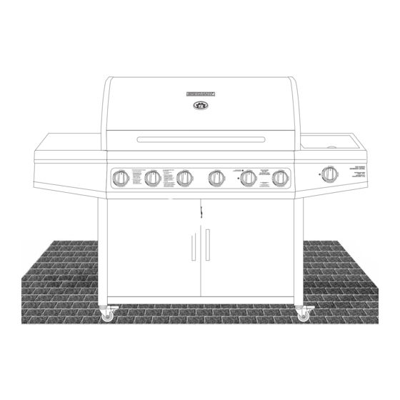
- Page 29 ® Brinkmann 6640 (Assembled)
- Page 30 PARA CUBIERTAS, ACCESORIOS Y OTROS PRODUCTOS, FAVOR DE VISITARNOS POR LA RED MUNDIAL EN: WARRANTY The Brinkmann Corporation warrants to the original pur chas er that the Brinkmann 6 Burner Gas Grill is free from defects due to workmanship or materials for: Ten-year: on stainless steel burners...
Need help?
Do you have a question about the 810-6640-S and is the answer not in the manual?
Questions and answers