Table of Contents
Advertisement
Quick Links
INSTRUCTIONS-PARTS LIST
This manual contains important
warnings and information.
READ AND KEEP FOR REFERENCE.
INSTRUCTIONS
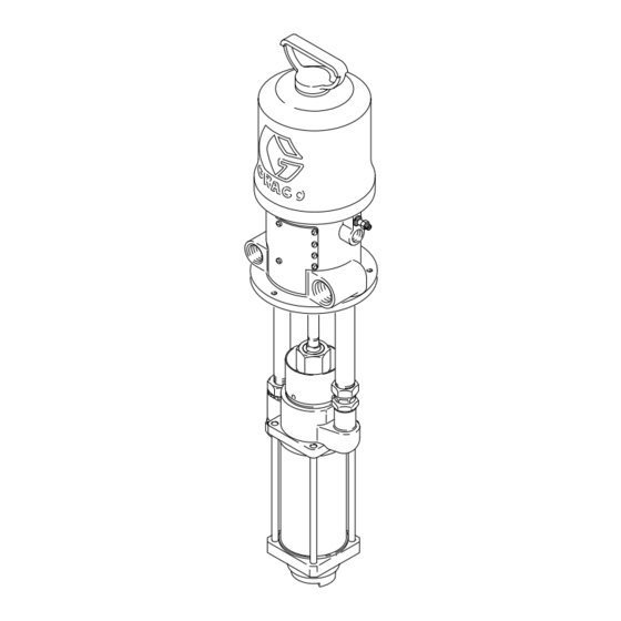
STUBBY SIZE
4:1 Ratio President Pump
400 psi (28 bar) Maximum Fluid Working Pressure
100 psi (7 bar) Maximum Air Input Pressure
Part No. 224-757, Series C
Carbon Steel, Leather Packed Pump
For Use in Lubrication Systems
Table of Contents
. . . . . . . . . . . . . . . . . . . . . . . . . . . . . . . . . . . . . .
. . . . . . . . . . . . . . . . . . . . . . . . . . . . . . . . . . . .
. . . . . . . . . . . . . . . . . . . . . . . . . . . . . . . . . . . . .
. . . . . . . . . . . . . . . . . . . . . . . . . . . . . . . . . .
. . . . . . . . . . . . . . . . . . . . . . . . . . . . . . .
. . . . . . . . . . . . . . . . . . . . . . . . . . . . . . . . . . . . . .
. . . . . . . . . . . . . . . . . . . . . . . . . . . . . . . . . . . . . . . .
. . . . . . . . . . . . . . . . . . . . . . . . . . . . . . . . . . .
. . . . . . . . . . . . . . . . . . . . . . . . . .
. . . . . . . . . . . . . . . . . . . . . . . . . . . . . . . .
. . . . . . . . . . . . . . . . . . . . . . . . . . . . . . .
GRACO INC. P.O. BOX 1441 MINNEAPOLIS, MN 55440-1441
2
5
8
10
11
12
13
14
14
15
16
. . . . . . . . . . . . . . . . .
16
COPYRIGHT 1992, GRACO INC.
Graco Inc. is registered to I.S. EN ISO 9001
308-159
Rev. C
Supersedes A
and PCN B
Advertisement
Table of Contents

Related Manuals for Graco President 224 757


Summary of Contents for Graco President 224 757
-
Page 1: Table Of Contents
Toll-Free Graco Phone Number ....GRACO INC. P.O. BOX 1441 MINNEAPOLIS, MN 55440–1441 COPYRIGHT 1992, GRACO INC. Graco Inc. is registered to I.S. EN ISO 9001... -
Page 2: Warnings
This equipment is for professional use only. Read all instruction manuals, tags, and labels before operating the equipment. Use the equipment only for its intended purpose. If you are not sure, call your Graco distributor. Do not alter or modify this equipment. - Page 3 WARNING FIRE AND EXPLOSION HAZARD Improper grounding, poor ventilation, open flames or sparks can cause a hazardous condition and result in a fire or explosion and serious injury. Ground the equipment and the object being lubricated. Refer to Grounding on page 5. If there is any static sparking or you feel an electric shock while using this equipment, stop dis- pensing immediately.
- Page 4 Notes...
-
Page 5: Installation
NOTE: Reference numbers and letters in parentheses in the text refer to the callouts in the figures and the parts drawing. NOTE: Always use Genuine Graco Parts and Acces- sories, available from your Graco distributor. If you supply your own accessories, be sure they are ade- quately sized and pressure rated for your system. - Page 6 Installation MAIN AIR LINE Pump Pump Runaway Valve Air Line Lubricator FLUID SUPPLY LINE Bleed-Type Master Air Valve (required, for pump) Air Regulator Air Line Filter G Bleed-Type Master Air Valve (for accessories) Fluid Drain Valve (required) Suction Kit Ground Wire (required; see page 5 for installation instructions) Fluid outlet is actually on the back side of the pump.
- Page 7 Installation Available Accessories (must be A pump runaway valve (B) automatically shuts off the pump if it starts running too fast. A pump which purchased separately) runs too fast can be seriously damaged. Air Line Accessories An air line lubricator (C) provides automatic air WARNING motor lubrication.
-
Page 8: Operation
Operation Pressure Relief Procedure If the pump is not immersed, fill the packing nut/wet- cup 1/2 full with a compatible solvent. Keep the cup filled at all times to help prevent the fluid you are WARNING pumping from drying on the exposed displacement rod and damaging the throat packings. - Page 9 Operation Prime the Pump 10. Relieve the pressure. Install the nozzle in the dispense valve, as explained in the dispense valve 1. See Fig. 2. Close all bleed-type air valves (D, G). manual. 2. Close the pump air regulator (E). WARNING 3.
-
Page 10: Maintenance
Maintenance Shutdown and Care of the Pump CAUTION Never leave water or water-base fluid in the pump WARNING overnight. If you are pumping water-base fluid, flush with water first, then with a rust inhibitor such as To reduce the risk of serious injury whenever you mineral spirits. -
Page 11: Troubleshooting
Troubleshooting 1. Relieve the pressure. WARNING To reduce the risk of serious injury whenever you are instructed to relieve pressure, always follow the 2. Check all possible problems and solutions before Pressure Relief Procedure on page 8. disassembling pump. Problem Cause Solution Pump fails to operate. -
Page 12: Service
Service Disconnecting the Displacement Pump 6. Turn on the air to the motor and run the pump slowly. Adjust the locknuts (14) on the return NOTE: For displacement pump repair instructions, mounting tube (11) as necessary until the pump refer to the separate displacement pump manual operates smoothly at minimum air pressure to the 307–983, supplied. -
Page 13: Parts
Parts Model 224–757, Series C 4:1 Ratio President Pump, Stubby Size Includes items 1–18 Part Description 205–038 AIR MOTOR, President See 306–982 for parts 190–069 ROD, connecting; 5.69” (144.5 mm) long 224–756 PUMP, displacement See 307–983 for parts 100–579 PIN, cotter 156–082 O-RING;... -
Page 14: Dimensions
Dimensions Mounting Hole Layout 0.375” 2.254” (9.52 mm) (57.25 mm) diameter 2.254” (57.25 mm) 3.188” (80.97 mm) 2.625” (66.67 mm) 5.250” (133.4 mm) 3/4 npt(f) 1” npt(f) return outlet NOTE: Use mounting gasket 161–322. Manual Change Summary Assembly Part Ref. Part No. -
Page 15: Technical Data
Technical Data Category Data Ratio Maximum fluid working pressure 400 psi (28 bar) Maximum air input pressure 100 psi (7 bar) Pump cycles per 1 gallon (3.8 liters) 8.25 Fluid flow at 60 cycles per minute 8 gpm (30 liters/min) Fluid inlet size 1–1/2 npt(f) Fluid outlet size... -
Page 16: Graco Warranty
Graco distributor to the original purchaser for use. Graco will, for a period of twelve months from the date of sale, repair or replace any part of the equipment determined by Graco to be defec- tive.
Need help?
Do you have a question about the President 224 757 and is the answer not in the manual?
Questions and answers