Table of Contents
Advertisement
Instructions - Parts List
Important Safety Instructions
Read all warnings and instructions in this manual. Save these instructions.
See page 26 for Maximum Working Pressures.
Dyna-Start
HYDRAULIC RECIPROCATOR AND PUMP
FOR LUBRICATING FLUIDS ONLY
1:1 Ratio Universal Pump and Reciprocator
Model 239882, Series A, Reciprocator Only
1500 psi (10 MPa, 102 bar) Maximum Hydraulic Input Pressure
1500 psi (10 MPa, 102 bar) Maximum Fluid Outlet Pressure
Model 224741, Series C, Stubby Length
1500 psi (10 MPa, 102 bar) Maximum Hydraulic Input Pressure
1500 psi (10 MPa, 102 bar) Maximum Fluid Outlet Pressure
Model 224742, Series C, 55-Gallon Length
1500 psi (10 MPa, 102 bar) Maximum Hydraulic Input Pressure
1500 psi (10 MPa, 102 bar) Maximum Fluid Outlet Pressure
Model 237653, Series B, Stainless Steel Stubby Length Pump
1000 psi (7 MPa, 69 bar) Maximum Hydraulic Input Pressure
1000 psi (7 MPa, 69 bar) Maximum Fluid Outlet Pressure
Table of Contents
. . . . . . . . . . . . . . . . . . . . . . . . . . . . . . . . . . .
. . . . . . . . . . . . . . . . . . . . . . . . . . . . . . . . . .
. . . . . . . . . . . . . . . . . . . . . . . . . . . . . . . . . .
. . . . . . . . . . . . . . . . . . . . . . . . . . . .
. . . . . . . . . . . . . . . . . . . . . . . . . . . . . . . . . . .
Models 224741, and 224742
Reciprocator Parts Drawing/List,
. . . . . . . . . . . . . . . . . . . . . . . . . . . . .
. . . . . . . . . . . . . . . . . . . . . . . . . . . . .
. . . . . . . . . . . . . . . . . . . . . . . . . . . . .
GRACO INC. P.O. BOX 1441 MINNEAPOLIS, MN 55440-1441
Copyright 1991, Graco Inc. is registered to I.S. EN ISO 9001
. . .
. . . . . . . .
. . . . . . . . .
. . . . . . . . . . . . . . . . .
. . . .
. . . . . . . .
. . . . . . . . . . . . . . . . . . .
. . . . . . . . . . . . . . . . . . . . . . .
Parts
2
5
9
11
12
18
19
Patent No. 4,383,475
20
Foreign Patents Pending
Patent 1984 Canada
22
Brevete 1984
23
24
25
26
27
28
28
308155M
06143C
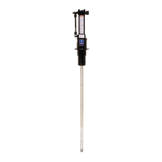
Model 224741 shown
Advertisement
Table of Contents

Related Manuals for Graco Dyna–Star 239882


Summary of Contents for Graco Dyna–Star 239882
-
Page 1: Table Of Contents
..... . . GRACO INC. P.O. BOX 1441 MINNEAPOLIS, MN 55440-1441 Copyright 1991, Graco Inc. is registered to I.S. EN ISO 9001... -
Page 2: Warnings
D Read all instruction manuals, tags, and labels before you operate the equipment. D Use the equipment only for its intended purpose. If you are not sure, call your Graco distributor. D Do not alter or modify this equipment. Use only genuine Graco parts and accessories. - Page 3 WARNING WARNING FLUID INJECTION HAZARD Fluid from the dispensing valve, leaks or ruptured components can inject fluid into your body and cause extremely serious injury, including the need for amputation. Fluid splashed in the eyes or on the skin can also cause serious injury. D Fluid injected into the skin might look like just a cut, but it is a serious injury.
- Page 4 WARNING WARNING FIRE AND EXPLOSION HAZARD Improper grounding, poor ventilation, open flames, or sparks can cause a hazardous condition and result in a fire or explosion and serious injury. D Ground the equipment and the object being dispensed to. Refer to Grounding on page 8. D If there is any static sparking or you feel an electric shock while using this equipment, stop dispensing immediately.
-
Page 5: Installation
Although the installation shown in Fig. 1 is only a guide for selecting and installing system components and accessories, some of the equipment is required, as noted in the key. For assistance in designing a system to suit your needs, contact your Graco distributor. 01843 Mount the pump to suit the type of installation planned. - Page 6 Installation CAUTION WARNING Keep The Hydraulic System Clean Mount the pump securely so that it cannot move The hydraulic supply system must be kept clean at around during operation. Failure to do so could all times to reduce the risk of damaging the recip- result in personal injury or equipment damage.
- Page 7 NOTE: Refer to Fig. 1 to locate the parts mentioned below. minimum 3/4” return line (F) on the reciprocator. Contact your Graco representative for details of line D Shut-off valves (H and L) are installed in the sizing. hydraulic supply and return lines. Order Part No.
- Page 8 Installation Grounding To ground the pump, remove the ground screw (Z) and insert through the eye of the ring terminal at end of To reduce the risk of static sparking, ground the pump. ground wire (Y). Fasten the ground screw back onto Check your local electrical code for detailed grounding the pump and tighten securely.
-
Page 9: Operation
60 cycles per minute. under high pressure can be injected through the NOTE: If Graco Part No. 236864 hydraulic fluid skin and cause serious injury. To reduce the risk of control is used, no adjustment is necessary. - Page 10 Operation If the Pump Leaks at the Fluid Fittings WARNING Maximum Working Pressures Models 239882, 224741, and 224742: Tighten To reduce the risk of serious injury, including the fittings (1, 5, 58), which are self-sealing and fluid injection and splashing in the eyes or on the have replaceable o-rings.
-
Page 11: Troubleshooting
Troubleshooting Note: Check all possible problems and solutions WARNING before disassembling the pump or reciprocator. To reduce the risk of serious injury whenever you are instructed to relieve pressure, always follow the Pressure Relief Procedure on page 9. Problem Cause Solution Pump won’t run. -
Page 12: Service
Service Replacing the Throat Seals See Fig. 5. NOTE: Replace these seals if fluid leaks excessively through the weep tube (B). This procedure can be done without disassembling the entire reciprocator. WARNING To reduce the risk of serious injury whenever you are instructed to relieve pressure, always follow the Pressure Relief Procedure on page 9. - Page 13 Service Disconnecting the Reciprocator and Models 239882, 224741, and 224742 Displacement Pump 36,37 Models 239882, 224741, and 224742 1. Flush the pump if possible, and stop it with the displacement rod in the lowest position. WARNING To reduce the risk of serious injury whenever you are instructed to relieve pressure, always follow the Pressure Relief Procedure on page 9.
- Page 14 Service Reciprocator Repair 3,39,2 NOTES 36,37 D The following reciprocator repair instructions are for Models 239882, 224741, and 224742. For Model 237653 instructions, see accompanying manual 307654. D Clean and inspect all parts for wear or damage. Replace parts as needed. For the best results, always replace all the o-rings and seals when you disassemble the pump.
- Page 15 Service 8. Visually inspect the spring (21). If there is wear or 3,39,2 damage, proceed with this step. Remove the nut (18), spring (21), and retainers (20) from the trip 36,37 rod (12). Reassemble with a retainer (20) on each end of the new spring (21).
- Page 16 Service ASSEMBLY A ASSEMBLY B 06148 Fig. 10 13. Lay Assembly A and Assembly B on the In steps 18 through 26, see Fig. 11. workbench. 17. Place the adapter (43) in a vise, and install the 14. Slide Assembly B into the center of the tool (D), seals as described on page 12.
- Page 17 Service 20. Place the cylinder (25) on the cylinder cap (32). 36,37 3,39,2 Install the piston (22) and valve assembly (31). NOTE: When you reinstall the cylinder (25), be sure the “P” port in the top cylinder cap of the spool valve assembly (31) and the port in the bottom cylinder cap (32) are in line with each other.
-
Page 18: Reciprocator Parts Drawing, Model 239882
Reciprocator Parts Drawing Model 239882, Series A, Hydraulic Reciprocator NOTE: See pages 12 to 20 for important assembly procedures and torque values. Ref 46 label 06144B 308155... -
Page 19: Reciprocator Parts List, Model 239882
Reciprocator Parts List Model 239882, Series A, Hydraulic Reciprocator Ref. Ref. Part No. Description Qty. Part No. Description Qty. 106470 ELBOW, straight thread, 222301 DISPLACEMENT ROD ASSY. 3/4–16 unf–2a x Contains 34a to 34c 3/4–16 unf–2a, 37_ flare 188078 ROD, displacement includes item 1a 105765 PACKING, o-ring... -
Page 20: Displacement Pump Repair, Models 239882, 224741, And 224742
Displacement Pump Repair (Models 239882, 224741, and 224742) Intake Valve. Displacement Pump. See Fig. 13. See Fig. 13. NOTE: Clean and inspect all parts for wear or damage WARNING as you disassemble them. Replace parts as needed. For the best results, always replace all the o-rings and To reduce the risk of serious injury, whenever you packings when you disassemble the pump. - Page 21 Displacement Pump Repair (Models 239882, 224741, and 224742) Intake Valve Reassembly 7. Grease the inside top of the displacement cylinder (108) opening. Thread the guide collar, Part No. 168085, onto the displacement cylinder. Slide the 0.2 ” packing assembly into the collar/cylinder. See Fig. (5 mm) 14.
-
Page 22: Displacement Pump Parts Drawing And List
Displacement Pump Parts Drawing and List Model 224741, Series C, Universal 1:1 Ratio Pump, Includes items 101 to 120 Model 224742, Series C, Hydraulic Reciprocator, Includes items 201 and 202 Ref. Ref. Part No. Description Qty. Part No. Description Qty. 224741 1:1 RATIO DYNA-STAR 239882... -
Page 23: Displacement Pump Repair, Model 237653
Displacement Pump Repair (Model 237653) Disassembly Reassembly When disassembling the pump, lay out all removed 1. Lubricate the throat packings and install them in parts in sequence, to ease reassembly. See Parts the outlet housing (16) one at a time as follows, Drawing on page 25. -
Page 24: Model 237653
Reciprocator Parts Drawing and List Model 237653, Series B NOTE: Reciprocator/pump Model 237653, Series B, has reciprocator Model 217222, Series J, which is shown here. Part Torque to Description 28 to 30 ft-lb (36 to 41 239874 CYLINDER CAP ASSY, upper N.m) 178179 WASHER, sealing... -
Page 25: Displacement Pump Parts Drawing And List
Displacement Pump Parts Drawing and List Model 237653, Series B NOTE: Reciprocator/pump Model 237653, Series B, has displacement pump Model 224344, Series F, which is shown here. Part Description 100063 PIN, cotter; 1/16” x 1/2”; sst 101917 BALL, 0.875” (22 mm); sst 164782 O-RING;... -
Page 26: Technical Data
Technical Data Maximum hydraulic fluid input pressure and maximum fluid output pressure Models 239882, 224741, and 224742 ... . 1500 psi (10 MPa, 102 bar) Model 237653 ........1000 psi (7 MPa, 69 bar) Maximum hydraulic fluid input volume . -
Page 27: Dimensions And Mounting Hole Layout
Dimensions and Mounting Hole Layout 3 in (76.2 mm) minimum diameter clearance hole 3/8 npt(f) hydraulic supply port 3/4 npt(f) hydraulic return port 14.75 in. (375 mm) Reciprocator 23.37 in. 3.536 in. Model (594 mm) 239882 (90.424 mm) Model 224741 217222 1/2 npt(f) fluid outlet port... -
Page 28: Graco Standard Warranty
Graco distributor to the original purchaser for use. With the exception of any special, extended, or limited warranty published by Graco, Graco will, for a period of twelve months from the date of sale, repair or replace any part of the equipment determined by Graco to be defective.
Need help?
Do you have a question about the Dyna–Star 239882 and is the answer not in the manual?
Questions and answers