Table of Contents
Advertisement
Quick Links
Instructions - - Parts List
HIGH VOLUME
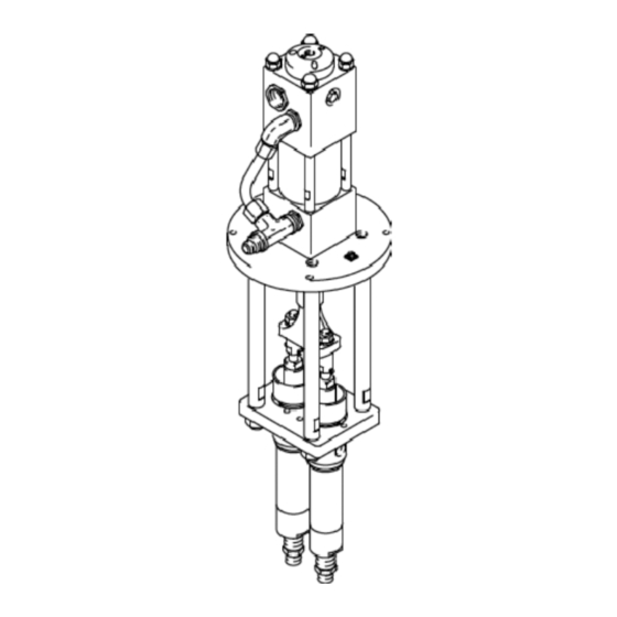
Plural Component Pumps
Air- -Powered Pumps
Part No. 246611, Series A (shown)
26:1 Ratio King Pump
2000 psi (13.8 MPa, 138 bar) Maximum Fluid Working Pressure
75 psi (0.5 MPa, 5 bar) Maximum Air Input Pressure
Part No. 224567, Series A
13:1 Ratio Bulldog Pump
1300 psi (9.1 MPa, 91 bar) Maximum Fluid Working Pressure
100 psi (0.7 MPa, 7 bar) Maximum Air Input Pressure
Hydraulic- -Powered Pumps
Part No. 217337, Series B (shown)
Viscount II Pump
2000 psi (13.8 MPa, 138 bar)
Maximum Fluid Working Pressure
1250 psi (8.7 MPa, 87.5 bar)
Maximum Hydraulic Input Pressure
Part No. 246041, Series A
Viscount II Pump
3000 psi (20.7 MPa, 207 bar)
Maximum Fluid Working Pressure
1150 psi (7.9 MPa, 79 bar)
Maximum Hydraulic Input Pressure
Read warnings and instructions.
GRACO INC. P.O. BOX 1441 MINNEAPOLIS, MN 55440- 1441
Copyright 1983, Graco Inc. is registered to I.S. EN ISO 9001
307547F
TI4247A
Advertisement
Table of Contents

Related Manuals for Graco 246611


Summary of Contents for Graco 246611
- Page 1 3000 psi (20.7 MPa, 207 bar) Maximum Fluid Working Pressure 1150 psi (7.9 MPa, 79 bar) Maximum Hydraulic Input Pressure TI4247A Read warnings and instructions. GRACO INC. P.O. BOX 1441 MINNEAPOLIS, MN 55440- 1441 Copyright 1983, Graco Inc. is registered to I.S. EN ISO 9001...
- Page 2 D This equipment is for professional use only. D Read all instruction manuals, tags, and labels before operating the equipment. D Use the equipment only for its intended purpose. If you are uncertain about usage, call your Graco distributor. D Do not alter or modify this equipment. Use only genuine Graco parts and accessories.
- Page 3 D Always wear protective eyewear, gloves, clothing and respirator as recommended by the fluid and solvent manufacturer. D Graco does not manufacture or supply any of the reactive chemical components that may be used in this equipment and is not responsible for their effects. Graco assumes no responsibility for loss, damage, expense or claims for personal injury or property damage, direct or consequential, arising from the use of such chemical components.
- Page 4 D Do not turn on or off any light switch in the spray area while operating or if fumes are present. D Do not operate a gasoline engine in the spray area. D Use only Graco heated hoses. Do not use the hose until the couplings are properly insulated and the hose abrasion cover is in place.
-
Page 5: General Information
All operators must thoroughly read all instruction TI1052 Fig. 2 manuals, tags, and labels before operating the equip- ment. 2. Fluid hoses: use only the Graco heated hose, Grounding which is electrically grounded. 3. Air and hydraulic hoses: use only electrically WARNING conductive hoses. -
Page 6: Hydraulic Pump Installation
Hydraulic Pump Installation Hydraulic Proportioner Fluid Pressure Relief Valves (required) Mounting Stand M Heated Hose Hydraulic Supply Line Fusion Spray Gun Hydraulic Return Line Hydraulic Supply Line Shutoff Valve Hydraulic Pressure Gauge Reactor Heater Fluid Inlet Valves Hydraulic Power Supply, with enclosed return line filter Feed Pumps W Fluid Supply Lines TI3697a... -
Page 7: Mounting The Pump
Install the following accessories in the order shown in of hydraulic fluid. Use only Graco approved hydraulic Fig. 3, using adapters as necessary. oil. Order Part No. 169236, 5 gallon (19 liter) or 207428, 1 gallon (3.8 liter). - Page 8 Air- -Powered Pump Installation Air- -Powered Proportioner Fluid Inlet Valves Mounting Stand Feed Pumps Air Supply Line Fluid Pressure Relief Valve (required) Air Line Filter M Heated Hose Air Regulator Fusion Spray Gun Air Pressure Gauge Reactor Heater G Bleed- -Type Master Air Valve W Fluid Supply Lines TI4246A Fig.
-
Page 9: System Accessories
Air- -Powered Pump Installation System Accessories Fluid Line Accessories Install the following accessories in the order shown in WARNING Fig. 4, using adapters as necessary. A pump air bleed valve (G) and a fluid pressure WARNING relief valve (L) in both fluid lines to the gun are required. -
Page 10: Pressure Relief Procedure
Add fluid as necessary to fill lines D are instructed to relieve the pressure, to replace the amount used. Use only Graco approved D shut off the pump, hydraulic oil. Order Part No. 169236, 5 gallon (19 liter) D stop spraying, or 207428, 1 gallon (3.8 liter). - Page 11 Operation Model 217337 Model 246041 Models 246611 and 224567 TI4285A TI4247A Fig. 5 307547...
- Page 12 Operation Prime the Pump WARNING NOTE: Use this procedure to prime the pump. To COMPONENT RUPTURE HAZARD prime the entire system including the hose and gun, To reduce the risk of overpressurizing refer to your system manual. your system, which could cause compo- nent rupture and serious injury, never 1.
-
Page 13: Maintenance
Maintenance Shutdown and Care of the Pump Flush with a fluid that is compatible with the fluid you are pumping and with the wetted parts in your system. Check with your fluid manufacturer or supplier for WARNING recommended flushing fluids and flushing frequency. To reduce the risk of serious injury whenever you CAUTION are instructed to relieve pressure, always follow the... - Page 14 Notes 307547...
-
Page 15: Troubleshooting
Troubleshooting 1. Relieve the pressure. WARNING To reduce the risk of serious injury whenever you are instructed to relieve pressure, always follow the 2. Check all possible problems and solutions before Pressure Relief Procedure on page 10. disassembling the pump. Problem Cause Solution... - Page 16 Service MODELS 217337, 246611, AND 224567 Reconnecting the Displacement Pumps NOTE: See the Parts drawings on pages 18 and 20. 1. Apply thread sealant to the threads of the coupler Disconnecting the Displacement Pumps (2) and screw it onto the motor. Place the gasket (3) on the yoke (4).
- Page 17 Service MODEL 246041 Reconnecting the Displacement Pumps NOTE: See the Parts drawing on page 19. 1. Apply thread sealant to the threads of the coupler Disconnecting the Displacement Pumps (2) and screw it onto the motor. Torque to 200--300 ft-lb (270--405 NSm). Place the gasket (3) on the NOTE: For displacement pump repair instructions, yoke (4).
- Page 18 Parts Part No. 217337, Series B Viscount II Plural Component Pump Part Torque to 40- -50 ft-lb (53- -68 NSm). Description Apply thread sealant. 217338 VISCOUNT HYDRAULIC MOTOR Lubricate. See manual 307158 172726 COUPLER 150429 GASKET, copper 181887 YOKE, connecting rod 181888 ROD, tie;...
- Page 19 Parts Part No. 246041, Series A Viscount II Plural Component Pump Part Torque to 53- -67 ft-lb (72- -90 NSm). Description Apply thread sealant. 235345 VISCOUNT HYDRAULIC MOTOR Lubricate. See manual 307158 172726 COUPLER Torque to 200- -300 ft-lb (270- -405 NSm). 150429 GASKET, copper Torque to 75- -85 ft-lb (101- -115 NSm).
- Page 20 Parts Part No. 246611, Series A Torque to 40- -50 ft-lb (53- -68 NSm). 26:1 King Plural Component Pump Apply thread sealant. (shown) Lubricate. Part Description 245111 KING AIR MOTOR See manual 309347 172726 COUPLER 150429 GASKET, copper 181887 YOKE, connecting rod 187056 ROD, tie;...
- Page 21 Dimensions Model 217337 Model 246041 Models 246611 and 224567 7352B TI4285A TI4247A Pump Model in. (mm) in. (mm) in. (mm) in. (mm) in. (mm) Hydraulic Hydraulic Fluid Optional Fluid Air Inlet Inlet Return Inlet Fluid Outlet Inlet 217337 44.02 16.06 12.87...
-
Page 22: Mounting Hole Layout
Mounting Hole Layout All Models Mounting Plate 11.28 in. (287 mm) Four 0.438 in. (11 mm) diameter holes, for shelf mounting 7.424 in. (x 4) (189 mm) 7356A 307547... -
Page 23: Technical Data
Part No. 217337 Viscount II Pump: 1250 psi (8.7 MPa, 87.5 bar) hydraulic Part No. 246041 Viscount II Pump: 1150 psi (7.9 MPa, 79 bar) hydraulic Part No. 246611 King Pump: 75 psi (0.5 MPa, 5 bar) air Part No. 224567 Bulldog Pump: 100 psi (0.7 MPa, 7 bar) air Pressure ratio Part No. -
Page 24: Graco Standard Warranty
With the exception of any special extended or limited warranty published by Graco, Graco will, for a period of twelve months from the date of sale, repair or replace any part of the equipment determined by Graco to be defective.
Need help?
Do you have a question about the 246611 and is the answer not in the manual?
Questions and answers