Table of Contents
Advertisement
Instructions–Parts List
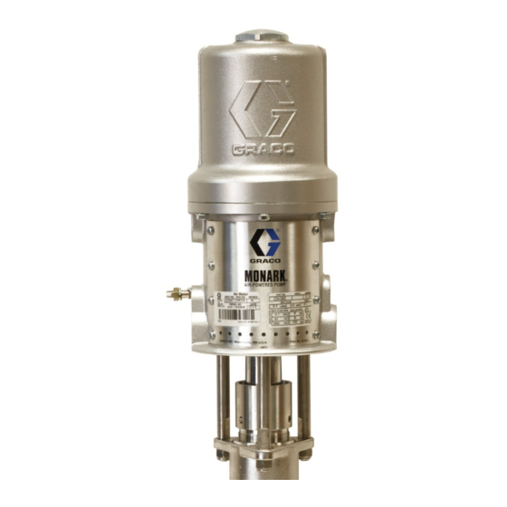
SEVERE-DUTY, UHMWPE/PTFE OR PTFE PACKED
Stainless Steel Pumps
Used to transfer or dispense low viscosity sealants and adhesives.
For professional use only.
Important Safety Instructions
Read all warnings and instructions in this manual.
Save these instructions.
UHMWPE/PTFE PACKED PUMPS
Model No. 224342, Series A
10:1 Ratio Presidentr Pump
1800 psi (13 MPa, 125 bar) Maximum Fluid Working Pressure
180 psi (1.3 MPa, 12.5 bar) Maximum Air Input Pressure
Model No. 224343, Series A
5:1 Ratio Monarkr Pump
600 psi (4.2 MPa, 42 bar) Maximum Fluid Working Pressure
120 psi (0.8 MPa, 8.4 bar) Maximum Air Input Pressure
UHMWPE/PTFE PACKED PUMPS
Model No. 261630, Series A
PTFE PACKED PUMPS
Model No. 247147, Series A
Model No. 902147, Series A
5:1 Ratio Monarkr Pump
600 psi (4.2 MPa, 42 bar) Maximum Fluid Working Pressure
120 psi (0.8 MPa, 8.4 bar) Maximum Air Input Pressure
Severe-Duty Displacement Pumps have an abrasion-resistant
displacement rod and cylinder. Refer to Technical Data on pages
22–23 for Wetted Parts information.
Model 224342 Shown
308116S
EN
0195
Advertisement
Table of Contents

Subscribe to Our Youtube Channel
Related Manuals for Graco 224342


Summary of Contents for Graco 224342
- Page 1 Read all warnings and instructions in this manual. Save these instructions. UHMWPE/PTFE PACKED PUMPS Model No. 224342, Series A 10:1 Ratio Presidentr Pump 1800 psi (13 MPa, 125 bar) Maximum Fluid Working Pressure 180 psi (1.3 MPa, 12.5 bar) Maximum Air Input Pressure Model No.
-
Page 2: Table Of Contents
D This equipment is for professional use only. D Read all instruction manuals, tags, and labels before operating the equipment. D Use the equipment only for its intended purpose. If you are not sure, contact your Graco distributor. D Do not alter or modify this equipment. - Page 3 WARNING SKIN INJECTION HAZARD Spray from the gun, leaks or ruptured components can inject fluid into your body and cause extremely serious injury, including the need for amputation. Fluid splashed in the eyes or on the skin can also cause serious injury. D Fluid injected into the skin might look like just a cut, but it is a serious injury.
- Page 4 WARNING FIRE AND EXPLOSION HAZARD Improper grounding, poor ventilation, open flames or sparks can cause a hazardous condition and re- sult in a fire or explosion and serious injury. D Ground the equipment and the object being sprayed. Refer to Grounding on page 6. D If there is any static sparking or you feel an electric shock while using this equipment, stop spray- ing immediately.
-
Page 5: Typical Installation
Typical Installation 0774A Pump Pump Runaway Valve Air Line Lubricator Bleed–Type Master Air Valve (required, for pump) Pump Air Regulator Air Line Filter Bleed–Type Master Air Valve (for accessories) Air Supply Hose Fluid Drain Valve (required) Fluid Filter Fluid Supply Hose Spray Gun Fluid Suction Hose Wall Bracket... -
Page 6: Installation
NOTE: Reference numbers and letters in parentheses in the text refer to the callouts in the figures and the parts drawing. NOTE: Always use Genuine Graco Parts and Acces- sories, available from your Graco distributor. If you supply your own accessories, be sure they are ade- quately sized and pressure rated for your system. - Page 7 The Typical Installation shown on page 5 is only a the Typical Installation, using adapters as necessary: guide for selecting and installing system components and accessories. Contact your Graco distributor for An air line lubricator (C) provides automatic air assistance in designing a system to suit your particular motor lubrication.
-
Page 8: Operation/Maintenance
Operation/Maintenance Pressure Relief Procedure 8. Leave the drain valve open until you are ready to spray again. WARNING If you suspect that the spray tip or hose is completely clogged, or that pressure has not been fully relieved PRESSURIZED EQUIPMENT HAZARD after following the steps above, very slowly loosen the The system pressure must be manually relieved to tip guard retaining ring or hose end coupling and... - Page 9 Hold a metal part of the spray gun (M) firmly to the side of a grounded metal pail and hold the trigger Keep the packing nut/wet-cup (2) filled with Graco open. Then open the pump’s bleed–type master air Throat Seal Liquid (TSL) or compatible solvent, to help valve (D).
- Page 10 Operation/Maintenance Air Motor Plate 0195 Fig. 3 308116...
-
Page 11: Service
Troubleshooting 1. Relieve the pressure. WARNING 2. Check all possible problems and solutions before To reduce the risk of serious injury whenever you disassembling pump. are instructed to relieve pressure, always follow the Pressure Relief Procedure on page 8. Problem Cause Solution Pump fails to operate. -
Page 12: Disconnecting The Displacement Pump
Fig 4. 0194 Lubricate. Model 224342: Torque to 20–30 ft-lb (27–41 NSm). 5. Start the pump and run it at about 40 psi (0.3 MPa, Models 224343, 902147, 247147: Torque to 10–15 ft-lb 2.8 bar) air pressure, to check that it is operating (14–20 NSm). -
Page 13: Displacement Pump Service
Service Displacement Pump Service Reassembly NOTE: On UHMWPE/PTFE packed pumps, the Disassembly packing order is one UHMWPE packing, two PTFE When disassembling the pump, lay out all removed packings, and one UHMWPE packing. On PTFE parts in sequence, to ease reassembly. Refer to Fig 5. packed pumps, all four packings are PTFE. - Page 14 Service Detail A: Throat Packings NOTE: Lips of v-packings must face down. 24* or 5* 24* or 5* See Detail A Detail B: Piston Packings See Detail B *23 or *20 *23 or *20 NOTE: Lips of v-packings must face up. 0191C Fig.
-
Page 15: Parts Drawings And Lists
Parts Model 224342, Series A 10:1 Ratio President Pump Includes items 101–111 Part Description 224341 DISPLACEMENT PUMP ASSY. See pages 18–19 for parts 102021 NUT, lock; 3/8–16; stainless steel 3 166237 ROD, tie; stainless steel; 3.5 in. (89 mm) shoulder to shoulder... -
Page 16: Model 224343 And 261630 Monark Pumps
Parts Model 224343, Series A (shown) 5:1 Ratio Monark Pump Includes items 101–111 Model 261630, Series A 5:1 Ratio Monark Pump Includes items 101–111 Part Description 224341 DISPLACEMENT PUMP ASSY. for Model 224343 only; See pages 18–19 for parts 254999 DISPLACEMENT PUMP ASSY. -
Page 17: Model 902147 And 247147 Monark Pumps
Parts Model 902147, Series A (shown) 5:1 Ratio Monark Pump Includes items 101–116 Model 247147, Series A 5:1 Ratio Monark Pump Includes items 101–111 Part Items 112–116 used on Model 902147 only. Description 15G976 DISPLACEMENT PUMP ASSY. See pages 20–21 for parts 102021 NUT, lock;... -
Page 18: Model 224341 And 254999 Displacement Pumps
Parts Model 224341, Series A (shown) Severe-Duty, UHMWPE/PTFE Packed Stainless Steel Displacement Pump Includes items 1–31 Model 254999, Series A Severe-Duty, UHMWPE/PTFE Packed Stainless Steel Displacement Pump Includes items 1–33 Items 6 and 7 used on Model 224341 only. 4* (224341 only) 33 (254999 only) 0190C 308116... - Page 19 Parts Model 224341, Series A Severe-Duty, UHMWPE/PTFE Packed Stainless Steel Displacement Pump Includes items 1–31 Model 254999, Series A Severe-Duty, UHMWPE/PTFE Packed Stainless Steel Displacement Pump Includes items 1–33 Ref. Ref. Part No. Description Qty. Part No. Description Qty. 205999 HOUSING, outlet;...
-
Page 20: Model 15G976 Displacement Pump
Parts Model 15G976, Series A Severe-Duty, PTFE Packed Stainless Steel Displacement Pump Includes items 1–31 0190C 308116... - Page 21 Parts Model 15G976, Series A Severe-Duty, PTFE Packed Stainless Steel Displacement Pump Includes items 1–31 Ref. Ref. Part No. Description Qty. Part No. Description Qty. 24C506 ROD, displacement; stainless steel1 205999 HOUSING, outlet; stainless steel 1 186988 GLAND, throat, female; 186995 PACKING NUT/WET-CUP;...
-
Page 22: Technical Data And Performance Charts
Technical Data 10:1 President Category Data Maximum fluid working pressure 1800 psi (12.5 MPa, 125 bar) Maximum air input pressure 180 psi (1.3 MPa, 12.5 bar) Pump cycles per 1 gallon (3.8 liters) Maximum recommended pump speed for continuous 60 cycles/min operation Maximum flow at continuous duty 3 gallon (11.4 liters) at 60 cycles/min... - Page 23 Technical Data 5:1 Monark Category Data Maximum fluid working pressure 600 psi (4.2 MPa, 42 bar) Maximum air input pressure 120 psi (0.8 MPa, 8.4 bar) Pump cycles per 1 gallon (3.8 liters) Maximum recommended pump speed for continuous 60 cycles/min operation Maximum flow at continuous duty 2.5 gallon (9.46 liters) at 60 cycles/min...
-
Page 24: Dimensions
Dimensions Mounting Hole Layout Model 224342 Shown 0.28 in. (7.1 mm) DIA. 4.38 in. (111.3 mm) DIA. 2.5 in. 5.0 in. (64 mm) (127 mm) 0775 1/2 npt(f) AIR INLET 1/2 npt(f) FLUID OUTLET 3/4 npt(f) FLUID INTAKE 0195 Pump... - Page 25 Notes 308116...
-
Page 26: Graco Standard Warranty
With the exception of any special, extended, or limited warranty published by Graco, Graco will, for a period of twelve months from the date of sale, repair or replace any part of the equipment determined by Graco to be defective.
Need help?
Do you have a question about the 224342 and is the answer not in the manual?
Questions and answers