Table of Contents
Advertisement
Quick Links
Instructions–Parts List
Overspray Masking Liquid
System
For airspray application of fluids.
Important Safety Instructions
Read all warnings and instructions in this manual.
Save these instructions.
2700 psi (18.6 MPa, 186 bar) Maximum Working Pressure
80–90 psi (560–630 kPa, 5.6–6.3 bar) recommended regulated air inlet pressure
System
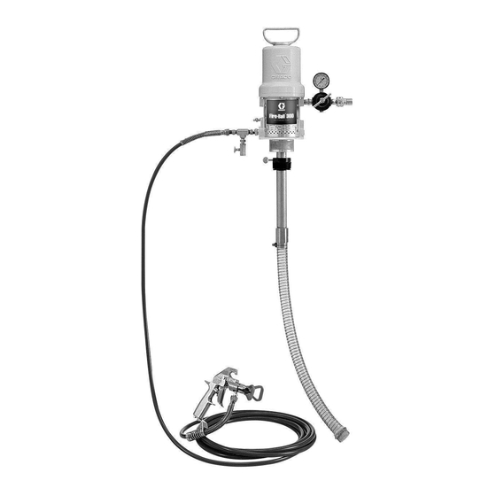
Model 224826
with Stainless Steel Pump*
Pump
Model 224825, Series A
Stainless Steel*
Ä Ä
Ä Ä
This pump is factory tested in oil. To avoid contami-
nating the masking liquid or the surface being
painted, flush the pump before immersing it in the
masking liquid. Use water only to flush. Paint sol-
vents will damage the seals. Follow the set-up
procedure carefully, and pay special attention to the
Flushing procedure on page 5.
7545A
308069N
CAUTION
ENG
Advertisement
Table of Contents

Subscribe to Our Youtube Channel
Related Manuals for Graco 224826


Summary of Contents for Graco 224826
- Page 1 Read all warnings and instructions in this manual. Save these instructions. 2700 psi (18.6 MPa, 186 bar) Maximum Working Pressure 80–90 psi (560–630 kPa, 5.6–6.3 bar) recommended regulated air inlet pressure System Model 224826 with Stainless Steel Pump* Pump Model 224825, Series A Stainless Steel* CAUTION This pump is factory tested in oil.
- Page 2 D This equipment is for professional use only. D Read all instruction manuals, tags, and labels before operating the equipment. D Use the equipment only for its intended purpose. If you are uncertain about usage, call your Graco distributor. D Do not alter or modify this equipment. Use only genuine Graco parts and accessories.
-
Page 3: Fire And Explosion Hazard
WARNING FIRE AND EXPLOSION HAZARD Improper grounding, poor ventilation, open flames or sparks can cause a hazardous condition and result in a fire or explosion and serious injury. D Ground the equipment and the object being sprayed. Refer to Grounding on page 4. D If there is any static sparking or you feel an electric shock while using this equipment, stop spray- ing immediately. -
Page 4: Installation
Spray Gun Safety Learn how to use the gun’s trigger safety latch before operating the system. The high pressure, airless spray gun supplied with this TO RELEASE THE LATCH system is equipped with a trigger safety latch. When FOR THE OFF SAFE, or set, this latch prevents the gun from being triggered spraying position, gently accidentally. -
Page 5: Prepare For Installation
Installation Prepare for installation Setup for initial flushing See Fig. 3. You must supply the following equipment to complete 5. Screw the air regulator assembly into the air inlet the installation of this system. of the motor. 1. An adjustable wrench and a screwdriver. 6. -
Page 6: Initial Flushing
Installation GROUND WIRE & CLAMP SPRAY GUN purchase separately AIR LINE QUICK DISCONNECT COUPLER QUICK DISCONNECT NIPPLE RAC V TIP GUARD AIR REGULATOR & GAUGE OUTLET NIPPLE SPRAY HOSE 7549A Fig. 3 Initial flushing 6. Release the trigger safety latch. 7. -
Page 7: Setup For Operation
Installation QUICK DISCONNECT NIPPLE GROUND WIRE & CLAMP purchase separately SPRAY GUN AIR LINE 5 GALLON PAIL QUICK DISCONNECT COUPLER RAC V TIP GUARD AIR REGULATOR & GAUGE VENT HOLE DRAIN BUNG HOLE VALVE DISPLACEMENT PUMP BUNG ADAPTER THUMBSCREW HOSE CLAMP SUCTION TUBE Ä... -
Page 8: Pressure Relief Procedure
Operation Pressure Relief Procedure 2. Close the air regulator and disconnect the air supply hose. WARNING 3. Disengage the trigger safety latch. Hold a metal part of the gun firmly to the side of a grounded INJECTION HAZARD metal waste pail and trigger it to relieve the fluid Fluid under high pressure can be in- pressure. - Page 9 Operation TIP GUARD SPRAY AIR LINE QUICK DISCONNECT COUPLER QUICK DISCONNECT NIPPLE AIR REGULATOR & GAUGE DRAIN VALVE DETAIL TIGHTEN TO CLOSE Ä Ä Fig. 5 Prime the system 7. Slowly open the air regulator until the pump is running slowly and smoothly. 1.
- Page 10 Operation Installing the spray tip CAUTION To avoid damaging the tip guard: 1. Be sure the trigger safety latch is engaged. D Never use a wrench to turn the plastic tip guard, 2. Install the tip cylinder. Hold the cylinder with the which causes internal damage.
- Page 11 Operation Changing spray tips Rotate handle up and toward back of the gun then trigger the gun to WARNING clear an obstruction. To reduce the risk of serious injury whenever you are instructed to relieve pressure, always follow the Pressure Relief Procedure on page 8. ARROW HANDLE SHOWN IN THE Relieve the pressure.
- Page 12 Operation Adjusting the spray pattern and spraying SPOTTY pressure. See Fig. 9. PATTERN GOOD – FULL INCREASE PATTERN NOTE: If the system is not primed, follow the proce- PRESSURE dure on page 9. TIP GUARD SHOWN 1. Set up a large piece of paper or cardboard to IN POSITION FOR spray on for testing the spray pattern.
-
Page 13: General Care
Maintenance General care 5. Connect the air line to the pump. 6. Release the trigger safety latch. WARNING 7. Aim the gun into the flushing pail and squeeze the To reduce the risk of serious injury whenever you gun trigger and hold it open. are instructed to relieve pressure, always follow the Pressure Relief Procedure on page 8. -
Page 14: Pinch Point
Maintenance Pump packing nut adjustment WARNING To reduce the risk of serious injury whenever you are instructed to relieve pressure, always follow the Pressure Relief Procedure on page 8. PISTON WARNING PINCH POINT Keep your hand and fingers away from the piston when it is moving. -
Page 15: Troubleshooting
Troubleshooting WARNING WARNING To reduce the risk of serious injury whenever you Never operate the pump with the warning plate (20) are instructed to relieve pressure, always follow the or the identification plate (40) removed. These Pressure Relief Procedure on page 8. plates protect your fingers from pinching or am- putation by moving parts in the air motor. - Page 16 Troubleshooting PROBLEM CAUSE SOLUTION Material drips steadily from weep Throat packing nut loose Tighten packing nut port in motor base Throat packing worn Replace packings Pump chattering Packing nut too tight Loosen packing nut Packing worn/material dried on I.D. of Inspect/replace packings packing Material dried on rod...
-
Page 17: Before You Start
Service Before you start: CAUTION 1. Have all necessary parts on hand. Always replace the glands and bearing when replacing the packings. To avoid damaging the cylinder wall, lift the cylinder Use all the parts in the repair kits for the best results straight up off of the piston. - Page 18 Service Reassembly 1. Clean all the parts in a compatible solvent and in- spect for wear or damage. Check the polished sur- faces of the piston, piston rod and cylinder wall for scratches or wear. A scored rod will cause premature packing wear and leaking.
-
Page 19: Cutaway View
Service PUSH TOGGLES (M) IN AND THEN UP (SHOWN IN THE DOWN POSITION HERE) 4. Install the poppets (52**) on the valve stems (45**). 34** Pull the exhaust valve poppets (53**) into the valve 33** actuator (35) and clip off the top part shown with dot- ted lines. -
Page 20: Displacement Pump Service
Displacement Pump Service Before you start: 5. Use a strap wrench on the riser tube (12) to screw it out of the air motor base (55). Carefully inspect the 1. Have all necessary parts on hand. Whenever you re- smooth inner surface of the cylinder for scoring or ir- place the packings, also replace the glands and regular surfaces. - Page 21 Displacement Pump Service Fig. 18 308069...
- Page 22 Parts Model 224825, Series A Repair Kits – purchase separately 235136 For displacement pump; includes items marked with a * 206728 For air motor includes items marked with ** 34** 33** 53** 32** 33** **36 52** 45** 39** LIPS OF V–PACKINGS MUST FACE DOWN...
- Page 23 Parts Model 224825, Series A 15:1 Fire–Ball 300 Pump, Stainless Steel (See Technical Data for additional wetted parts.) Includes items 2–74 NO. PART NO. DESCRIPTION NO. PART NO. DESCRIPTION 103075* BALL, sst, 0.44” (11.2 mm) dia. 187749 . ROD, piston 101859* BALL, sst, 0.75”...
- Page 24 Parts Model 224826 Stainless Steel System (See Technical Data for additional wetted parts.) Includes items 1 to 4 PART NO. DESCRIPTION PART NO. DESCRIPTION 286621 . SPRAY TIP, Size 621 224825 15:1 FIRE–BALL 300 PUMP installed in tip guard See pages 22 and 23 for parts 243161 .
-
Page 25: Technical Data
Technical Data Category Data Maximum working pressure 2700 psi (18.6 MPa, 186 bar) Fluid pressure ratio 15:1 Air operating range 40–180 psi (0.3–1.2 MPa, 3–12 bar) Air motor effective diameter 3 in. (76 mm) Stroke 3 in. (76 mm) Air consumption 17 cfm/gallon pumped at 100 psi (0.476 m /liter at 0.7 MPa, 7 bar)’... -
Page 26: Graco Standard Warranty
Graco distributor to the original purchaser for use. With the exception of any special, extended, or limited warranty published by Graco, Graco will, for a period of twelve months from the date of sale, repair or replace any part of the equipment determined by Graco to be defective.
Need help?
Do you have a question about the 224826 and is the answer not in the manual?
Questions and answers