
Subscribe to Our Youtube Channel
Related Manuals for protech Prox-1260 M4


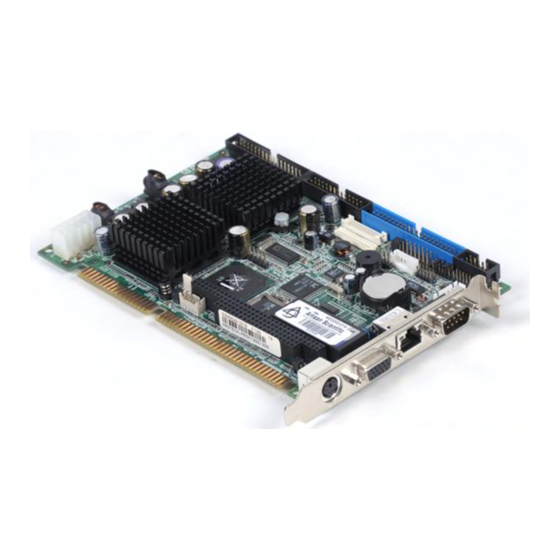
Summary of Contents for protech Prox-1260 M4
- Page 1 USER’S MANUAL ProX-1260 VIA EDEN Half-size Embedded Card With VGA/LAN/SOUND Prox-1260 M4...
- Page 2 Copyright Notice Prox-1260 Half-size CPU Board With VGA / Sound / LAN OPERATION MANUAL COPYRIGHT NOTICE This operation manual is meant to assist both Embedded Computer manufacturers and end-users in installing and setting up the system. The information contained in this document is subject to change without any prior notice.
- Page 3 Copyright Notice FCC NOTICE This equipment has been tested and found to comply with the limits for a Class A digital device, pursuant to part 15 of the FCC Rules. These limits are designed to provide reasonable protection against harmful interference when the equipment is operated in a commercial environment.
- Page 4 Contents TABLE OF CONTENTS CHAPTER 1 INTRODUCTION About This Manual ............System Specifications ........... Safety Precautions ............CHAPTER 2 HARDWARE CONFIGURATION Jumper & Connector Quick Reference Table ....Component Locations ........... How to Set the Jumpers ..........COM Port Connector ............ RS232/422/485 (COM2) Selection .......
-
Page 5: Table Of Contents
Contents 2-33 SSD Memory Mapping Selection ……………………. 2-23 2-34 IRQ12 Release Selection ……………………………... 2-23 2-35 LVDS LCD Connector ……………………………….. 2-24 2-36 LVDS Panel Power Selection ………………………... 2-25 CHAPTER 3 SOFTWARE UTILITIES Introduction ..............VGA Driver Utility ............Flash BIOS Update ............LAN Driver Utility …........... - Page 6 Contents APPENDIX B TECHNICAL SUMMARY Block Diagram ................. Interrupt Map ................RTC & CMOS RAM Map ............Timer & DMA Channels Map ..........I/O & Memory Map ..............APPENDIX C TROUBLESHOOTING Troubleshooting for Error Messages ........Troubleshooting for POST Code ..........
- Page 7 CHAPTER INTRODUCTION This chapter gives you the information for Prox-1260. It also outlines the System specifications. Section includes: About This Manual System Specifications Safety precautions Experienced users can skip to chapter 2 on page 2-1 for a Quick Start. Page:1-1...
- Page 8 Chapter 1 Introduction 1-1. ABOUT THIS MANUAL Thank you for purchasing our Prox-1260, Half Size CPU Board enhanced with VGA/Sound/LAN, is fully PC / AT/ATX compatible. The Prox-1260 provides faster processing speed, greater expandability and can handle more tasks than before. This manual is designed to assist you how to install and set up the system.
- Page 9 Chapter 1 Introduction 1-2. SYSTEM SPECIFICATIONS CPU : VIA Eden 400/533/733 MHz (or up to 1.X GHz) processors Auto detect voltage regulator. SYSTEM CHIPSET : VIA VT8606, VT82C686B MEMORY : Up to 512MB SDRAM One 144-pin SO-DIMM socket on board. CACHE : Built-in CPU.
- Page 10 Chapter 1 Introduction DISPLAY : Built-in VIA VT8606, supports CRT, TTL & LVDS. Integrated S3®’s Savage4™ 2D/3D/Video Accelerator. Optimized Shared Memory Architecture (SMA). 2~32 MB Frame Buffer using system memory. Supports simultaneous display of CRT & LCD. Interface: One 15-pin connector supports for CRT Monitor. One 41-pin connector support 18 bit or 24 bit panel for TTL.
- Page 11 Chapter 1 Introduction PARALLEL PORT : Supports SPP, ECP, EPP Function mode. Bi-directional parallel port. SOUND FUNCTION : Integrated Sound Blaster / DirectSound AC97 audio. Dual Full duplex direct sound channels bet. system memory & AC97 link. 32 byte FIFO of each Direct Sound Channel. Realtek ALC202A, AC97 SoundMAX®...
- Page 12 Chapter 1 Introduction INTERRUPT LEVELS : OPERATING TEMPERATURE : 0 to 60°C (32°F to 140°F) SYSTEM POWER REQUIREMENT : DC Voltage: +5V Standby, minimum +4.75V, maximum +5.25V. DC Ampere: 0.04A. (ATX Support) DC Voltage: +5V, minimum +4.75V, maximum +5.25V. DC Ampere: 2.4A. DC Voltage: +12V, minimum +11.4V, maximum +12.6V.
- Page 13 CHAPTER HARDWARE CONFIGURATION ** QUICK START ** Helpful information describes the jumper & connector settings, and component locations. This section includes: Jumper & Connector Quick Reference Table Component Locations Configuration and Jumper settings Connector‘s Pin Assignments Page 2-1...
- Page 14 Chapter 2 Hardware Configuration 2-1. JUMPER & CONNECTOR QUICK REFERENCE TABLE COM Connector ..........………. COM1, COM2 RS232/422/485 (COM2) Selection ......……... Keyboard/Mouse Connector ………..……..…..... Keyboard/Mouse Selection ……………………………. JP10 External Speaker Connector ........……… EXKB1 Inverter Connector ……………………………………... INV1 Power LED Connector ………………………………… JP4 (1-3) Reset Connector ...........……..
- Page 15 Chapter 2 Hardware Configuration 2-2. COMPONENT LOCATIONS LCD2 LVDS1 VT8606 Battery 8100BL ED E N FAN1 JP10 Prox-1260 Connector, Jumper and Component locations ′ Page: 2-3 Prox-1260 USER S MANUAL...
- Page 16 Chapter 2 Hardware Configuration 2-3. HOW TO SET THE JUMPERS You can configure your board by setting the jumpers. Jumper is consists of two or three metal pins with a plastic base mounted on the card, and by using a small plastic "cap", Also known as the jumper cap (with a metal contact inside), you are able to connect the pins.
- Page 17 Chapter 2 Hardware Configuration JUMPER DIAGRAMS JUMPER SETTINGS ′ Page: 2-5 Prox-1260 USER S MANUAL...
- Page 18 Chapter 2 Hardware Configuration 2-4. COM PORT CONNECTOR There are two COM ports enhanced in this board namely: COM1 and COM2. COM1 is fixed for RS-232, while COM2 is selectable for RS- 232/422/485. COM1 : COM1 Connector The COM1 Connector assignments are as follows : ASSIGNMENT COM1 COM2 : COM2 Connector...
- Page 19 Chapter 2 Hardware Configuration 2-5. RS232/422/485 (COM2) SELECTION JP2 : RS-232/422/485 Selection COM2 is selectable for RS-232, 422, 485 function. The jumper settings are as follows : COM 2 JUMPER SETTING JUMPER FUNCTION (pin closed) ILLUSTRATION RS-232 Open 1-2, 5-6, 7-8, 9-10 11-12, 13-14, 15-16 RS-422 17-18, 19-20...
- Page 20 Chapter 2 Hardware Configuration 2-7. KEYBOARD/MOUSE SELECTION JP10 : Keyboard or Mouse Selection. If User select to use Y-Cable, please set the jumper same as AT Keyboard. The selections are as follows : DEVICE JUMPER SETTING JUMPER TYPE (pin closed) ILLUSTRATION KEYBOARD/Y-Cable JP10...
- Page 21 Chapter 2 Hardware Configuration 2-9. INVERTER CONNECTOR INV1 : Inverter Connector The pin assignment is as follows: ASSIGNMENT +12V +12V ENABKL (Inverter backlight ON/OFF control signal) 2-10. POWER LED CONNECTOR JP4 (1-3) : Power LED Connector The pin assignment is as follows: PW_LED ASSIGNMENT PW_LED...
- Page 22 Chapter 2 Hardware Configuration 2-12. HARD DISK DRIVE LED CONNECTOR JP4 (2-4) : Hard Disk Drive LED Connector The pin assignments are as follows : HDD _LED ASSIGNMENT HDD Active Signal 2-13. POWER BUTTON JP4 (5-6) : Power Button for ATX power. The pin assignments are as follows: PW_BN ASSIGNMENT...
- Page 23 Chapter 2 Hardware Configuration 2-15. SLPBTN CONNECTOR JP4 (13-14) : SLPBTN Connector The pin assignments are as follows: SLPBTN ASSIGNMENT SLPBTN 2-16. FAN CONNECTOR FAN1 : FAN Connector The pin assignments are as follows: FAN1 ASSIGNMENT +12V FAN speed monitor 2-17.
- Page 24 Chapter 2 Hardware Configuration 2-18. VGA CONNECTOR VGA1 : VGA Connector The pin assignments are as follows: ASSIGNMENT GREEN BLUE I2CCK HSYNC VSYNC I2CDA ′ Page: 2-12 Prox-1260 USER S MANUAL...
- Page 25 Chapter 2 Hardware Configuration 2-19. LCD CONNECTOR LCD1 : LCD Connector The pin assignments are as follows : ASSIGNMEN ASSIGNMENT LCD_VCC5 LCD_VCC5 FPVS FPDEN FPHS FPCLLK LCD_VCC3 LCD_VCC3 ENABKL ENVDD +12V +12V ′ Page: 2-13 Prox-1260 USER S MANUAL...
- Page 26 Chapter 2 Hardware Configuration LCD2 : LCD Connector The pin assignments are as follows : ASSIGNMEN ASSIGNMENT +12V +12V LCD_VCC LCD_VCC ENVDD FPCCLK FPVS FPDEN FDHS ENABKL LCD_VCC LCD_VCC ′ Page: 2-14 Prox-1260 USER S MANUAL...
- Page 27 Chapter 2 Hardware Configuration 2-20. UNIVERSAL SERIAL BUS CONNECTOR CN2 : Universal Serial Bus Connector USB connector of this board can support two USB ports. The pin assignments are as follows: ASSIGNMENT 5V_SB USBDT0- USBDT0+ 5V_SB USBDT1− USBDT1+ 2-21. CLEAR CMOS SELECTION JP7 : Clear CMOS Selection The selections are as follows: JUMPER...
- Page 28 Chapter 2 Hardware Configuration 2-22. FLOPPY DISK DRIVE CONNECTOR FDD1 : Floppy Disk Drive Connector You can use a 34-pin daisy-chain cable to connect two FDDs. On one end of this cable there is a 34-pin flat cable to attach the FDD on the board, the other side attaches to two FDDs.
- Page 29 Chapter 2 Hardware Configuration 2-23. HARD DISK DRIVE CONNECTOR IDE1 : Hard Disk Drive Connector The pin assignments are as follows: IDE1 ASSIGNMENT ASSIGNMENT IDERST PDD7 PDD8 PDD6 PDD9 PDD5 PDD10 PDD4 PDD11 PDD3 PDD12 PDD2 PDD13 PDD1 PDD14 PDD0 PDD15 DDREQA -DIOWA...
- Page 30 Chapter 2 Hardware Configuration 2-24. PRINTER CONNECTOR LPT1 : Printer Connector As to link the Printer to the card, you need a cable to connect both DB25 connector and parallel port. The pin assignments are as follows : ASSIGNMENT ASSIGNMENT AUTFE ERROR INIT...
- Page 31 Chapter 2 Hardware Configuration 2-25. RESET/NMI/CLEAR WATCHDOG SELECTION JP8 : Reset/NMI/Clear Watchdog Selection The selections are as follows: FUNCTION JUMPER SETTING JUMPER (pin closed) ILLUSTRATION RESET CLEAR WATCHDOG ***Manufacturing Default is set as Reset. ′ Page: 2-19 Prox-1260 USER S MANUAL...
- Page 32 Chapter 2 Hardware Configuration 2-26. LAN CONNECTOR UTP1 : LAN Connector The pin assignments are as follows: ASSIGNMENT ISOLATED GND ISOLATED GND PULL HI LED-Green (Speed) PULL HI LED-Yellow (Link) 2-27. ATX POWER CONNECTOR PW2 : Power Connector The pin assignments are as follows : ASSIGNMENT +12V 5V_SB...
- Page 33 Chapter 2 Hardware Configuration 2-28. ATX BACKPLANE CONNECTOR JP9 : ATX Backplane Connector. The pin assignments are as follows : ASSIGNMENT 5V_SB PS_ON 2-29. AT/ATX POWER SELECTION J2, J3 : AT/ATX Power Selection The selections are as follows: JUMPER SETTING POWER JUMPER (pin closed)
- Page 34 Chapter 2 Hardware Configuration 2-30. SOUND CONNECTOR CN1 : Sound Connector This connector is used to connect the microphone, line-in, and line-out through our adapter card. The pin assignments are as follows: ASSIGNMENT MIC-IN GND_AUD LINE-L GND_LOUT SPK-L MIC-VDD GND_AUD LINE-R GND_LOUT SPK-R...
- Page 35 Chapter 2 Hardware Configuration 2-32. SOLID-STATE DISK SOCKET SSD: 32pin Disk-on-chip Socket The pin assignments are as follows: ASSIGNMENT ASSIGNMENT SA12 SA10 SA11 ′ Page: 2-23 Prox-1260 USER S MANUAL...
-
Page 36: Ssd Memory Mapping Selection
Chapter 2 Hardware Configuration 2-33. SSD MEMORY MAPPING SELECTION JP1 : SSD Memory Mapping Selections A 32-pin SSD socket supports Disk-on-Chip up to 144MB. This PnP Flash ROM SSD can be install as one of user’s hard disk drive. The SSD Memory Mapping Selections are as follows: JUMPER SETTING SSD Memory Map JUMPER... -
Page 37: Lvds Lcd Connector
Chapter 2 Hardware Configuration 2-35. LVDS CONNECTOR LVDS1 : LVDS Connector. The pin assignments are as follows: ASSIGNMENT ASSIGNMENT LCD_VCC LCD_VCC LCD_VCC ′ Page: 2-25 Prox-1260 USER S MANUAL... -
Page 38: Lvds Panel Power Selection
Chapter 2 Hardware Configuration 2-36. LVDS/ LCD2 PANEL POWER SELECTION JP3 : LCD_VCC Power Selection. The selections are as follows: JUMPER SELECTION JUMPER SETTING ILLUSTRATION LCD_VCC3 LCD_VCC5 ′ Page: 2-26 Prox-1260 USER S MANUAL... -
Page 39: Chapter 3 Software Utilities
CHAPTER SOFTWARE UTILITIES This chapter comprises the detailed information of VGA driver, LAN driver, sound driver, and Flash BIOS update. It also describes how to install the watchdog timer configuration. Section includes: VGA Driver Utility Flash BIOS Update LAN Driver Utility Sound Driver Utility Watchdog Timer Configuration Page: 3-1... -
Page 40: Introduction
Chapter 3 Software Configuration 3-1. INTRODUCTION Enclosed with our Prox-1260 package is our driver utility, which may comes in a form of a CD ROM disc or floppy diskettes. For CD ROM disc user, you will only need some of the files contained in the CD ROM disc, please kindly refer to the following chart: Filename Purpose... -
Page 41: Flash Bios Update
Chapter 3 Software Configuration 3-3. FLASH BIOS UPDATE 3-3-1. System BIOS Update: Users of Prox-1260 can use the program “Awdflash.exe” contained in the Utility Disk for system BIOS and VGA BIOS update. 3-3-2. To update VGA BIOS for LCD Flat Panel Display: As Prox-1260 user, you have to update the VGA BIOS for your specific LCD flat panel you are going to use. - Page 42 Chapter 3 Software Configuration FLASH MEMORY WRITER v7.XX (C) Award Software 2000 All Rights Reserved For 8604-686B-6A6LLP69C-0 DATE: 04/23/2001 Flash Type - MXIC 29F002(N)T /5V File Name to Program: C30bxxxx.bin Checksum: XXXXX Error Message : Are You Sure To Program (Y/N) Select "Y", and the BIOS will be renewed.
-
Page 43: Lan Driver Utility
Chapter 3 Software Configuration 3-4. LAN DRIVER UTILITY 3-4-1. Introduction Prox-1260 Embedded Board is enhanced with LAN function that can support various network adapters. Installation programs for LAN drivers are listed as follows: 1. Win 95/98/2000/XP program 2. Win NT program 3. - Page 44 Chapter 3 Software Configuration 2. Install LAN Driver to Windows NT 3.0/4.0 (1) In the Main group of NT, select the “Control Panel” icon. (2) In the Control Panel window, choose the “Network” icon. (3) In the Network Settings dialog box, choose the “Add adapter” button.
-
Page 45: Sound Driver Utility
Chapter 3 Software Configuration 3-5. SOUND DRIVER UTILITY 3-5-1. Introduction The sound function enhanced in this system is fully compatible with Windows 9x/98SE/ME, Windows NT, DOS, OS2, Linux, Windows 2000 and Windows XP. Below, you will find the content of the Sound driver : 1. -
Page 46: Watchdog Timer Configuration
Chapter 3 Software Configuration 3-6. WATCHDOG TIMER CONFIGURATION This board has watchdog timer function for monitoring whether the system is still work or not after a period of time. The user can select watchdog timer to system reset or NMI (Non Maskable interrupt) depending on the jumper set in “Reset/NMI/Clear Watchdog Selection”... -
Page 47: Chapter 4 Award Bios Setup
CHAPTER AWARD BIOS SETUP This chapter shows how to set up the Award BIOS. Section includes: Introduction Entering Setup The Standard CMOS Features The Advanced BIOS Features The Advanced Chipset Features Integrated Peripherals Power Management Setup PNP/PCI Configuration PC Health Status Frequency/Voltage Control Load Fail-Safe Defaults Load Optimized Defaults... -
Page 48: Introduction
Chapter 4 Award BIOS Setup 4-1. INTRODUCTION This chapter will show you the function of the BIOS in managing the features of your system. The Prox-1260 half size Embedded Board is equipped with the BIOS for system chipset from Award Software Inc. This page briefly explains the function of the BIOS in managing the special features of your system. -
Page 49: Entering Setup
Chapter 4 Award BIOS Setup 4-2. ENTERING SETUP When the system is powered on, the BIOS will enter the Power-On Self Test (POST) routines and the following message will appear on the lower screen: PRESS <DEL> TO ENTER SETUP, ESC TO SKIP MEMORY TEST As long as this message is present on the screen you may press the <Del>... -
Page 50: The Standard Cmos Features
Chapter 4 Award BIOS Setup 4-3. THE STANDARD CMOS FEATURES Highlight the〝STANDARD CMOS FEATURES〞and press the <ENTER> key and the screen will display the following table: Phoenix - AwardBIOS CMOS Setup Utility Standard CMOS Features Date (mm:dd:yy) Fri Jun 20 2003 Item Help Time (hh:mm:ss) 10 : 40 : 20... - Page 51 Chapter 4 Award BIOS Setup IDE Primary Master / Slave: IDE Secondary Master / Slave: The BIOS can automatically detect the specifications and optimal operating mode of almost all IDE hard drives. When you select type AUTO for a hard drive, the BIOS detect its specifications during POST, every time system boots.
- Page 52 Chapter 4 Award BIOS Setup LBA (Logical Block Addressing): During drive accesses, the IDE controller transforms the data address described by sector, head and cylinder number into a physical block address, significantly improving data transfer rates. For drives greater than 1024 cylinders. DRIVE A AND DRIVE B: Select the type of floppy disk drive installed in your system.
- Page 53 Chapter 4 Award BIOS Setup HARD DISK ATTRIBUTES: Type Cylinders Heads V-P comp LZone Sect Capacity 65535 65535 65535 65535 65535 65535 65535 0000 0000 65535 1024 1023 0000 65535 1024 65535 1023 1224 65535 1223 1224 65535 1223 1224 65535 1223 1024...
-
Page 54: The Advanced Bios Features
Chapter 4 Award BIOS Setup 4-4. THE ADVANCED BIOS FEATURES Choose the〝ADVANCED BIOS FEATURES〞in the main menu, the screen shown as below. Phoenix - AwardBIOS CMOS Setup Utility Advanced BIOS Features Virus Warning [Disabled] Item Help CPU Internal Cache [Enabled] External Cache [Enabled] Menu Level ►... - Page 55 Chapter 4 Award BIOS Setup A brief introduction of each setting in the BIOS FEATURES SETUP program is given below. VIRUS WARNING : This item allows you to choose the Virus Warning feature for IDE Hard Disk boot sector protection. If this function is enabled and someone attempt to write data into this area, BIOS will show a warning message on screen and alarm beep.
- Page 56 Chapter 4 Award BIOS Setup GATE A20 OPTION: This entry allows you to select how the gate A20 is handled. When Normal was set, a pin in the keyboard controller controls Gate A20. And when Fast was set, the chipset controls Gate A20. TYPEMATIC RATE SETTING: Enable this item if you wish to be able to configure the characteristics of your keyboard.
- Page 57 Chapter 4 Award BIOS Setup VIDEO BIOS SHADOW : Determines whether video BIOS will be copied to RAM. However, it is optional depending on chipset design. Video Shadow will increase the video speed. C8000-CBFFF SHADOW ~ DC000-DFFFF SHADOW: These categories determine whether option ROMs will be copied to RAM. An example of such option ROM would be support of on-board SCSI.
-
Page 58: Advanced Chipset Features
Chapter 4 Award BIOS Setup 4-5. ADVANCED CHIPSET FEATURES Choose the〝ADVANCED CHIPSET FEATURES〞from the main menu, the screen shown as below. Phoenix - AwardBIOS CMOS Setup Utility Advanced Chipset Features Item Help DRAM Timing by SPD [Enabled] x DRAM Clock Host CLK x SDRAM Cycle Length Menu Level ►... - Page 59 Chapter 4 Award BIOS Setup It also coordinates communications between conventional ISA bus and the PCI bus. It must be stated that these items should never need to be altered. The default settings have been chosen because they provide the best opera- ting conditions for the system.
- Page 60 Chapter 4 Award BIOS Setup AGP-4X MODE: This item allows you to enable or disable the AGP-4X Mode. AGP DRIVING CONTROL: This item allows you to adjust the AGP driving force. Choose Manual to key in an AGP Driving Value in the next selection. This field is recommended to set in Auto for avoiding any error in your system.
- Page 61 Chapter 4 Award BIOS Setup PCI#2 ACCESS #1 RETRY: When disabled, PCI#2 will not be disconnected until access finishes. When Enabled, PCI#2 will be disconnected if max retries are attempted without success. AGP MASTER 1 WS WRITE: When Enabled, writes to the AGP (Accelerated Graphics Port) are executed with one wait state.
-
Page 62: Integrated Peripherals
Chapter 4 Award BIOS Setup 4-6. INTEGRATED PERIPHERALS Choose〝INTEGRATED PERIPHERALS〞from the main setup menu, a display will be shown on screen as below: Phoenix - AwardBIOS CMOS Setup Utility Integrated Peripherals On-Chip IDE Channel0 [Enabled] Item Help IDE Prefetch Mode [Enabled] ►... - Page 63 Chapter 4 Award BIOS Setup PRIMARY MASTER/SLAVE PIO: The four IDE PIO fields allow you to set a PIO mode (0-4) for each of the four IDE devices that the onboard IDE interface supports. Modes 0 through 4 provide successively increased performance. In Auto mode, the system automatically determines the best mode for each device.
- Page 64 Chapter 4 Award BIOS Setup TX, RX INVERTING ENABLE: This item allows you to enable TX, RX inverting which depends on different H/W requirement. This field is not recommended to change its default setting for avoiding any error in your system. ONBOARD PARALLEL PORT: This item allows you to determine access onboard parallel port controller with which I/O address.
-
Page 65: Power Management Setup
Chapter 4 Award BIOS Setup 4-7. POWER MANAGEMENT SETUP Choose〝POWER MANAGEMENT SETUP〞option on the main menu, a display will be shown on screen as below : Phoenix - AwardBIOS CMOS Setup Utility Power Management Setup ACPI function [Disabled] Item Help ►Power Management [Press Enter] PM Control by APM... - Page 66 Chapter 4 Award BIOS Setup VIDEO OFF OPTION: This category determines the power-saving modes during which the monitor goes blank: ALWAYS ON Monitor remains on during power-saving modes. SUSPEND → OFF Monitor blanked when system enters Suspend mode. SUSP,STBY → OFF Monitor blanked when system enters either Suspend or Standby mode.
- Page 67 Chapter 4 Award BIOS Setup When ON of LPT & COM, any activity from one of the listed system peripheral devices or IRQs wakes up the system. HDD & FDD: When ON of HDD & FDD, any activity from one of the listed system peripheral devices wakes up the system.
-
Page 68: Pnp/Pci Configuration
Chapter 4 Award BIOS Setup 4-8. PNP/PCI CONFIGURATION Choose 〝PNP/PCI CONFIGURATION〞 from the main menu, a display will be shown on screen as below: Phoenix - AwardBIOS CMOS Setup Utility PnP/PCI Configurations PNP OS Installed [Yes] Item Help Reset Configuration Data [Disabled] Menu Level ►... - Page 69 Chapter 4 Award BIOS Setup RESET CONFIGURATION DATA: Normally, you leave this field Disabled. Select Enabled to reset Extended System Configuration Data (ESCD) when you exit Setup if you have installed a new add-on and the system configuration has caused such a serious conflict that the operating system cannot boot.
-
Page 70: Pc Health Status
Chapter 4 Award BIOS Setup 4-9. PC HEALTH STATUS Choose 〝PC HEALTH STATUS〞 from the main menu, a display will be shown on screen as below: Phoenix - AwardBIOS CMOS Setup Utility PC Health Status Current CPU Temp. 48ºC/ 118ºF Item Help Current CPU FAN Speed 0 RPM... -
Page 71: Frequency/Voltage Control
Chapter 4 Award BIOS Setup 4-10. FREQUENCY/VOLTAGE CONTROL Choose 〝FREQUENCY/VOLTAGE CONTROL〞 from the main menu, a display will be shown on screen as below: Phoenix - AwardBIOS CMOS Setup Utility Frequency Control VIA Eden Clock Ratio [Default] Item Help Auto Detect DIMM/PCI Clk [Enabled] Spread Spectrum [Disabled]... -
Page 72: Load Fail-Safe Defaults
Chapter 4 Award BIOS Setup 4-11. LOAD FAIL-SAFE DEFAULTS By pressing the <ENTER> key on this item, you get a confirmation dialog box with a message similar to the following: Load Fail-Safe Defaults ( Y/N ) ? N To use the BIOS default values, change the prompt to "Y" and press the <Enter >... -
Page 73: Password Setting
Chapter 4 Award BIOS Setup 4-13. PASSWORD SETTING User is allowed to set either supervisor or user password, or both of them. The difference is that the supervisor password can enter and change the options of the setup menus while the user password can enter only but do not have the authority to change the options of the setup menus. -
Page 74: Save & Exit Setup
Chapter 4 Award BIOS Setup 4-14. SAVE & EXIT SETUP After you have completed adjusting all the settings as required, you must remember to save these setting into the CMOS RAM. To save the settings, select “SAVE & EXIT SETUP” and press <Enter>, a display will be shown as follows: Phoenix - AwardBIOS CMOS Setup Utility ►Standard CMOS Features... -
Page 75: Exit Without Saving
Chapter 4 Award BIOS Setup 4-15. EXIT WITHOUT SAVING If you wish to cancel any changes you have made, you may select the “EXIT WITHOUT SAVING” and the original setting stored in the CMOS will be retained. The screen will be shown as below: Phoenix - AwardBIOS CMOS Setup Utility ►Standard CMOS Features ►Frequency/Voltage Control... - Page 76 Chapter 4 Award BIOS Setup ′ Page: 4-30 Prox-1260 USER S MANUAL...
-
Page 77: Appendix A Expansion Bus
APPENDIX EXPANSION BUS This appendix indicates you the pin assignments. Section includes: PC-104 Connector Pin Assignment ISA BUS Pin Assignment Page: A-1... - Page 78 Appendix A Expansion Bus PC-104 CONNECTOR PIN ASSIGNMENT 104AB, 104CD : PC-104 Connector The PC-104 can support multi-pieces of PC-104 modules. It has two connectors : one (104AB) consists of 64 pin; the other one (104CD) consists of 40 pin, both of them are dual-in-line headers The pin assignments for connector 104AB &...
- Page 79 Appendix A Expansion Bus ISA BUS PIN ASSIGNMENT The ISA BUS for this card is called “Gold Fingers”. It is divided into two sets : one consists of 62 pins; the other consists of 36 pins. The pin assignments are as follows : ASSIGNMENT ASSIGNMENT ASSIGNMENT...
- Page 80 Appendix A Expansion Bus Page: A-4 Prox-1260 USER‘S MANUAL...
- Page 81 APPENDIX TECHNICAL SUMMARY This section introduce you the maps concisely. Section includes: Block Diagram Interrupt Map RTC & CMOS RAM Map Timer & DMA Channels Map I / O & Memory Map Page: B-1...
-
Page 82: Appendix B Technical Summary Block Diagram
Appendix B Technical Summary BLOCK DIAGRAM VIA C3 EDEN PROCESSOR HOST BUS Monitor ADDR VIA VT8606 MEMORY CACHE DRAM DATA 1 SO-DIMM AND PCI/AGP CNTL MODULES CONTROLLER Floppy LAN1 82C686B K.B./Mouse IDE1 ISA BUS CONTROLLER Parallel Port COM1~2 RJ45 Volt. Sensor Temp. -
Page 83: Interrupt Map
Appendix B Technical Summary INTERRUPT MAP ASSIGNMENT System TIMER interrupt from TIMER-0 Keyboard output buffer full Cascade for IRQ 8-15 Serial port 2 / Modem Serial port 1 Parallel port 2 / Sound Blaster Floppy Parallel port 1 RTC clock Available Available Available... -
Page 84: Rtc & Cmos Ram Map
Appendix B Technical Summary RTC & CMOS RAM MAP CODE ASSIGNMENT Seconds Second alarm Minutes Minutes alarm Hours Hours alarm Day of week Day of month Month Year Status register A Status register B Status register C Status register D Diagnostic status byte Shutdown byte Floppy Disk drive type byte... -
Page 85: Timer & Dma Channels Map
Appendix B Technical Summary TIMER & DMA CHANNELS MAP Timer Channel Map : Timer Channel Assignment System timer interrupt DRAM Refresh request Speaker tone generator DMA Channel Map : DMA Channel Assignment Available Available / Sound Blaster Floppy Available / ECP Cascade for DMA controller 1 Available Available... -
Page 86: I/O & Memory Map
Appendix B Technical Summary I/O & MEMORY MAP Memory Map : MEMORY MAP ASSIGNMENT 0000000-009FFFF System memory used by DOS and application 00A0000-00BFFFF Display buffer memory for VGA/ EGA / CGA / MONOCHROME adapter 00C0000-00DFFFF Reserved for I/O device BIOS ROM or RAM buffer. -
Page 87: Troubleshooting For Error Messages
APPENDIX TROUBLE- SHOOTING This section outlines the error messages that may occur when you operate the system. It also gives you some tips on how to solve the problems. Section includes: Troubleshooting for Error Messages Troubleshooting for POST Code Page: C-1... - Page 88 Appendix C Troubleshooting TROUBLESHOOTING FOR ERROR MESSAGE The following information inform you the error messages and the trouble shooting. Please adjust your systems according to the messages below. And make sure all the components and connectors are in proper position and firmly attached.
- Page 89 Appendix C Troubleshooting DISKETTE DRIVES OR TYPES MISMATCH ERROR : When the diskette drive type is different from CMOS, please run setup or configure the drive again. ERROR ENCOUNTERED INITIALIZING HARD DRIVE : When you can‘t initialize the hard drive. Assure the adapter is installed correctly and all cables are correctly and firmly attached.
- Page 90 Appendix C Troubleshooting MEMORY VERIFYING ERROR : It indicates an error verifying a value already written to memory. Use the location along with your system's memory map to locate the bad chip. OFFENDING ADDRESS MISSING : This message is used in connection with the I/O CHANNEL CHECK and RAM PARITY ERROR messages when the segment that has caused the problem cannot be isolated.
- Page 91 Appendix C Troubleshooting TROUBLESHOOTING FOR POST CODES When you power on your PC, and the screen display nothing. You have to insert the POST Card for test. The address for ISA POST port is 80h. Make sure the card is in correct slot. The lists below indicate you the error messages.
- Page 92 Appendix C Troubleshooting 0A : 1. Initialize the first 32 interrupt vectors with corresponding Interrupt handlers Initialize INT no from 33-120 with Dummy(Spurious) Interrupt Handler. 2. Issue CPUID instruction to identify CPU type. 3. Early Power Management initialization (OEM specific). 0B : 1.Verify the RTC time is valid or not.
- Page 93 Appendix C Troubleshooting 15 : Test 8259 interrupt mask bits for channel 1. 16 : Test 8259 interrupt mask bits for channel 2. 19 : Test 8259 functionality. 30 : Detect Base Memory & Extended Memory Size. 31 : 1. Test Base Memory from 256K to 640K. 2.
- Page 94 Appendix C Troubleshooting 4E : If there is any error detected (such as video, kb..), show all the error messages the screen & wait for user to press <F1> key. 4F : 1. If password is needed, ask for password. 2.
- Page 95 Appendix C Troubleshooting 62 : 1.Setup daylight saving according to Setup value. 2.Program the NumLock, typematic rate & typematic speed according to Setup setting. 63 : 1. If there is any changes in the hardware configuration, update the ESCD information (PnP BIOS only). 2.
- Page 96 Appendix C Troubleshooting ′ Page: C-10 Prox-1260 USER S MANUAL...
- Page 97 Appendix C Troubleshooting ′ Page: C-11 Prox-1260 USER S MANUAL...
- Page 98 Appendix C Troubleshooting PRINTED IN TAIWAN ′ Page: C-12 Prox-1260 USER S MANUAL...
Need help?
Do you have a question about the Prox-1260 M4 and is the answer not in the manual?
Questions and answers