Advertisement
Quick Links
Advertisement

Related Manuals for protech ProX-1680


Summary of Contents for protech ProX-1680
- Page 1 USER’S MANUAL ProX-1680 Dual Socket 370 Processor Embedded Card W/ VGA / Dual LAN...
- Page 2 Copyright Notice ProX-1680 Dual Socket 370 Full-sized Embedded Card With VGA / Dual LAN OPERATION MANUAL COPYRIGHT NOTICE This operation manual is meant to assist both Embedded Computer manufacturers and end users in installing and setting up the system. The information contained in this document is subject to change without any notice.
- Page 3 Contents TABLE OF CONTENTS CHAPTER 1 INTRODUCTION About This Manual ............System Specification ............. Safety Precautions ............CHAPTER 2 HARDWARE CONFIGURATION Jumper & Connector Quick Reference Table ....Component Locations ........... How to Set the Jumpers ..........CPU FSB Selection …………………………………... ATX / AT Power Selection …………………………...
- Page 4 Contents 2-31 Reset/NMI/Clear Watchdog Selection ……………….. 2-27 2-32 Power Connector ............2-28 2-33 LVDS Power Selection …….………………………… 2-28 2-34 PPCI Connector ………………………………………. 2-29 2-35 Panel Power Connector ………………………………. 2-30 2-36 Memory Installation ………………………………….. 2-30 2-37 Panel Type Selection …………………………………. 2-31 CHAPTER 3 SOFTWARE UTILITIES Introduction …………...........
-
Page 5: Table Of Contents
Contents APPENDIX B TECHNICAL SUMMARY Block Diagram ................. Interrupt Map ................RTC & CMOS RAM Map ............Timer & DMA Channels Map ..........I/O & Memory Map ..............APPENDIX C TROUBLE SHOOTING Trouble Shooting for Error Messages ........Trouble Shooting for POST Codes .......... - Page 6 CHAPTER INTRODUCTION This chapter gives you the information for Prox-1680. It also outlines the System specification. Section includes: About This Manual System Specifications Safety precautions Experienced users can skip to chapter 2 on page 2-1 for Quick Start. Page:1-1...
- Page 7 Chapter 1 Introduction 1-1. ABOUT THIS MANUAL Thank you for purchasing our Prox-1680 Dual Socket 370 Embedded Card equipped with VGA / Dual LAN, which is fully PC / AT compatible. Prox- 1680 provides faster processing speed, greater expandability and can handle more task than before.
- Page 8 UNIVERSAL SERIAL BUS : Universal Serial Bus Connector on board. Supports up to 2 USB ports. BUS SUPPORT : External ISA/PCI BUS (PICMG Spec.); PPCI BUS Internal AGP Bus for VGA. Internal PCI Bus for LAN. ′ Page: 1-3 Prox-1680 USER S MANUAL...
- Page 9 Dual port, support for 10BaseT/100 BaseTx PCI Ethernet. Support Wake-On-LAN function. SERIAL PORT : Two high speed 16550 Compatible UARTs with Send / Receive 16 Byte FIFOs. COM1 for RS232. COM2 for RS232/422/485. ′ Page: 1-4 Prox-1680 USER S MANUAL...
- Page 10 LAN LED indicator. BUS SPEED : ISA Bus 8MHz PCI Bus 33MHz PPCI Bus 33MHz 12Mbit/sec DMA CONTROLLER : 82C37 x 2 DMA CHANNELS : INTERRUPT CONTROLLERS : 82C59 x 2 INTERRUPT LEVELS : ′ Page: 1-5 Prox-1680 USER S MANUAL...
- Page 11 3. Disconnect power when you change any hardware devices. For instance, when you connect a jumper or install any cards, a surge of power may damage the electronic components or the whole system. ′ Page: 1-6 Prox-1680 USER S MANUAL...
- Page 12 CHAPTER HARDWARE CONFIGURATION ** QUICK START ** Helpful information describes the jumper & connector settings, and component locations. Section includes: Jumper & Connector Quick Reference Table Component Locations Configuration and Jumper settings Connector’s Pin Assignments Page 2-1...
- Page 13 ATX Power Signal Connector …..…………………….. Reset/NMI/Clear Watchdog Selection .………….…….. Power Connector ………………………………………. LVDS Power Selection ………………………………... PPCI Connector ……………..………………….……… PPCI Panel Power Connector ………………………………. JP12 Memory Installation ........…..……… DIMM1, DIMM2 …………………………………… DIMM3 Panel Type Selection ………………………………….. ’ Page: 2-2 Prox-1680 USER S MANUAL...
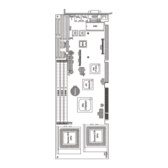
- Page 14 Chapter 2 Hardware Configuration 2-2. COMPONENT LOCATIONS LAN1 LAN2 Prox-1680 Connector, Jumper and Component locations ’ Page: 2-3 Prox-1680 USER S MANUAL...
- Page 15 You can connect PIN1 & PIN2 to create one setting and shorting. You can either connect PIN2 & PIN3 to create another setting. The same jumper diagrams are applied all through this manual. The figure below shows what the manual diagrams look and what they represent. ’ Page: 2-4 Prox-1680 USER S MANUAL...
- Page 16 Jumper Block looks like this JUMPER SETTINGS 2 pin Jumper close(enabled) Looks like this 3 pin Jumper 2-3 pin close(enabled) Looks like this Jumper Block 1-2 pin close(enabled) Looks like this ’ Page: 2-5 Prox-1680 USER S MANUAL...
- Page 17 *** Manufactory default --- ATX. The default is set as ATX, if you wish to use the AT Power, you must remember to disable the ACPI Function in the Power Management found in BIOS Setup. ’ Page: 2-6 Prox-1680 USER S MANUAL...
- Page 18 The pin assignment is as follows : ASSIGNMENT COM 1 COM2 : COM2 Connector COM2 is selectable as RS-232/422/485. The pin assignment is as follows : ASSIGNMENT RS-232 RS-422 RS-485 COM 2 RTS- RTS+ CTS+ CTS- ’ Page: 2-7 Prox-1680 USER S MANUAL...
- Page 19 Jumper Settings Jumper Illustrations Function (pin closed) Open RS-232 1-2, 5-6, 7-8, 9-10 RS-422 11-12, 13-14, 15-16 17-18, 19-20 1-3, 4-6, 7-8, 9-10 RS-485 11-12, 13-14, 15-16 17-18, 19-20 *** Manufactory default --- RS-232. ’ Page: 2-8 Prox-1680 USER S MANUAL...
- Page 20 Chapter 2 Hardware Configuration 2-8. SOLID-STATE DISK SOCKET SSD: 32pin Disk-on-chip Socket The pin assignments are as follows: ASSIGNMENT ASSIGNMENT SA12 SA10 SA11 ’ Page: 2-9 Prox-1680 USER S MANUAL...
- Page 21 Flash ROM SSD can be install as one of user’s hard disk drive. The SSD Memory Mapping Selections are as follows: JUMPER SETTING JUMPER SELECTION (pin closed) ILLUSTRATION D0000h-D1FFFh D4000h-D5FFFh D8000h-D9FFFh DC000h-DDFFFh *** Manufactory default --- D0000h-D1FFFh. ’ Page: 2-10 Prox-1680 USER S MANUAL...
- Page 22 For Y-Cable user, please set the jumper same as AT keyboard. The jumper settings are as follows: DEVICE JUMPER SETTING JUMPER TYPE (pin closed) ILLUSTRATION KEYBOARD PS/2 MOUSE *** Manufactory default -- AT Keyboard ’ Page: 2-11 Prox-1680 USER S MANUAL...
- Page 23 EXKB : External Keyboard Connector The pin assignment is as follows : ASSIGNMENT KBCLK KBDATA EXKB 2-13. RESET CONNECTOR Panel1(18,20) : Reset Connector. The pin assignment is as follows : ASSIGNMENT RESET GROUND ’ Page: 2-12 Prox-1680 USER S MANUAL...
- Page 24 Panel1 (12,14) : Hard Disk Drive LED Connector The pin assignment is as follows : ASSIGNMENT HDD_LED ACTIVE SIGNAL 2-15. ATX POWER BUTTON Panel1 (13,15) : Hard Disk Drive LED Connector The pin assignment is as follows : ASSIGNMENT PWR_BTN ’ Page: 2-13 Prox-1680 USER S MANUAL...
- Page 25 Panel1(2,4,6,8) : External Speaker Connector The pin assignment is as follows : ASSIGNMENT SPEAKER SIGNAL 2-17. GREEN FUNCTION CONNECTOR Panel1(17,19) : Green Function Connector The pin assignment is as follows : ASSIGNMENT -EXTSMI ’ Page: 2-14 Prox-1680 USER S MANUAL...
- Page 26 Note: To clear CMOS data, user must power-off the computer and set the jumper to “Clear CMOS” as illustrated above. After five to six seconds, set the jumper back to “Normal” and power-on the computer. ’ Page: 2-15 Prox-1680 USER S MANUAL...
- Page 27 There are two CPU FAN connector found on this board. FAN1 : CPU Fan1 connector The pin assignment is as follows: ASSIGNMENT +12V CPUFAN1 FAN2 : CPU Fan2 connector The pin assignment is as follows: ASSIGNMENT +12V CPUFAN2 ’ Page: 2-16 Prox-1680 USER S MANUAL...
- Page 28 Chapter 2 Hardware Configuration 2-21. VGA CRT CONNECTOR VGA : VGA CRT Connector The pin assignments are as follows: ASSIGNMENT GREEN BLUE HSYNC VSYNC ’ Page: 2-17 Prox-1680 USER S MANUAL...
- Page 29 DDC2B electrical interface that can be shared with the standard 15-pin DDC2B compliant VGA connector (if present). The pin assignments are as follows : TMDS ASSIGNMENT ASSIGNMENT TX1+ TX2+ TX1- TX2- SHLD1 SHLD2 SHLDC SHLD0 TXC+ TX0+ TXC- TX0- DDC_DAT DDC_CLK ’ Page: 2-18 Prox-1680 USER S MANUAL...
- Page 30 The pin assignments are as follows : ASSIGNMEN ASSIGNMENT LVDS2 TXU1+ TXU1- TXU3+ TXU3- TXU0+ TXU0- TXCLKU+ TXCLKU- PANEL VDD TXU2+ TXU2- CHARGE 24bit and below panel used LVDS1, for 36/48bit panel used both LVDS1 and LVDS2 connector. ’ Page: 2-19 Prox-1680 USER S MANUAL...
- Page 31 Chapter 2 Hardware Configuration 2-24. HARD DISK DRIVE CONNECTOR IDE1: Hard Disk Drive Connector The Prox-1680 possesses two HDD connectors, IDE1 and IDE2. The pin assignments are as follows: IDE1 ASSIGNMENT ASSIGNMENT IDERST IDEREQ0 IDED7 IDEIOW IDED8 IDED6 IDEIOR IDED9...
- Page 32 ASSIGNMENT ASSIGNMENT IDERST IDEREQ1 IDED7 IDEIOW IDED8 IDED6 IDEIOR IDED9 IDED5 IDERDY IDED10 IDED4 IDEDACK- IDED11 IDED3 IRQ14 IDED12 IDED2 IDEA1 IDED13 SD_80P IDED1 IDEA0 IDED14 IDEA2 IDED0 IDECS1S IDED15 IDECS3S IDELEDS N.C. ’ Page: 2-21 Prox-1680 USER S MANUAL...
- Page 33 34-pin flat cable to attach the FDD on the board, and the other side is attaches two FDDs. The pin assignments are as follows : ASSIGNMENT ASSIGNMENT RWC- INDEX MOA- STEP TRK0 WRPRT RDATA HEAD DSKCHG ’ Page: 2-22 Prox-1680 USER S MANUAL...
- Page 34 As to link the Printer to the card, you need a cable to connect both DB25 connector and parallel port. The pin assignments are as follows : ASSIGNMENT ASSIGNMENT AUTFE ERROR INIT SLCTIN BUSY SLCT ’ Page: 2-23 Prox-1680 USER S MANUAL...
- Page 35 This connector can connect up to two USB port. The pin assignments are as follows: ASSIGNMENT USBP0− USBP0+ USB1 USBP1− USBP1+ 2-28. IRDA CONNECTOR IRDA1: IrDA (Infrared) Connector The pin assignments are as follows: ASSIGNMENT IRRX IRTX ’ Page: 2-24 Prox-1680 USER S MANUAL...
- Page 36 Master, which means one of the PCI Bus Masters is occupied. The When LAN Bus Master is same as 1st PCI Slot on the backplane. the LAN chipset is on-board, the 1st PCI slot on backplane would fail even if LAN function is disable. ’ Page: 2-25 Prox-1680 USER S MANUAL...
- Page 37 ISOLATED GND PULL HI LED – Green PULL HI LED - Yellow 2-30. ATX POWER SIGNAL CONNECTOR JP7 : ATX Power Signal Connector The pin assignments are as follows: ASSIGNMENT +5V SB PWR_ON ’ Page: 2-26 Prox-1680 USER S MANUAL...
- Page 38 Non-Maskable Interrupt, is used for serious conditions that demand the processor’s immediate attention, it cannot be ignored by the system unless it is shut off specifically. To clear NMI command, user should short the “Clear Watchdog” pin via push button. ’ Page: 2-27 Prox-1680 USER S MANUAL...
- Page 39 The pin assignments are as follows: ASSIGNMENT +12V +5V SB PS_ON -12V 2-33. LVDS POWER SELECTION JU1: LVDS Power Selection The selections are as follows: SELECTION JUMPER SETTING JUMPER (pin closed) ILLUSTRATION VDD +3.3V VDD +5V ’ Page: 2-28 Prox-1680 USER S MANUAL...
- Page 40 Chapter 2 Hardware Configuration 2-34. PPCI CONNECTOR You will find a PPCI connector in our Prox-1680. This connector is used to connect our SCSI daughter boards. The pin assignments are as follows: PPCI ASSIGNMENT ASSIGNMENT AD10 AD11 AD12 AD13 AD14...
- Page 41 2-35. PANEL POWER CONNECTOR JP12: Panel Power Connector The pin assignment is as follows: ASSIGNMENT LCD +12V LCD +5V 2-36. MEMORY INSTALLATION Prox-1680 CPU Card can support DDR SDRAM-PC2100 in 3 DIMM socket. DRAM BANK CONFIGURATION DIMM 1 DIMM 2 DIMM3 TOTAL MEMORY...
- Page 42 800x600 pixel LVDS 1024x768 pixel LVDS 1280x1024 pixel ***Manufacturing Default – PanelLink™. When user intends to use both PanelLink™ and LVDS, the jumper setting should be set in accordance of the LVDS setting. ’ Page: 2-31 Prox-1680 USER S MANUAL...
- Page 43 Chapter 2 Hardware Configuration ’ Page: 2-32 Prox-1680 USER S MANUAL...
- Page 44 CHAPTER SOFTWARE UTILITIES This chapter comprises the detailed information of VGA driver, LAN driver, and Flash BIOS update. It also describes how to install the watchdog timer configuration. Section includes: VGA Driver Utility Flash BIOS Update LAN Driver Utility VIA 4in1 Service Pack Watchdog Timer Configuration Page: 3-1...
- Page 45 Chapter 3 Software Configuration 3-1. INTRODUCTION Enclosed with our Prox-1680 package is our driver utility, which may comes in a form of a CD ROM disc or floppy diskettes. For CD ROM disc user, you will only need some of the files contained in the CD ROM disc, please...
- Page 46 Utility Disk for system BIOS and VGA BIOS update. 3-3-2. To update VGA BIOS for LCD Flat Panel Display: As Prox-1680 user, you have to update the VGA BIOS for your specific LCD flat panel you are going to use. For doing this, you need two files.
- Page 47 Select "Y", and the BIOS will be renewed. When you are refreshing the BIOS, do not turn off or reset the system, or you will damage the BIOS. After you have completed all the programming, the screen displays the table below: ′ Page:3-4 Prox-1680 USER S MANUAL...
- Page 48 File Name to Program: B2xxxxxx.bin Checksum: XXXXX Reset System or Power off to accomplish update process! F1: Reset F10: Exit Please reset or power off the system, and then the Flash BIOS is fully implemented. ′ Page:3-5 Prox-1680 USER S MANUAL...
- Page 49 Chapter 3 Software Configuration 3-4. LAN DRIVER UTILITY 3-4-1. Introduction Prox-1680 Embedded Card is enhanced with dual LAN function that can support various network adapters. Installation programs for LAN drivers are listed as follows: 1. Win 95/98 program 2. Win NT program 3.
- Page 50 These four drivers are: VIA Registry (INF) Driver, VIA AGP VxD driver, VIA ATAPI Vendor Support Driver and VIA PCI IRQ Miniport Driver. 1. Win 95 program 2. Win NT program 3. Win 2000 program 4. Win 98/SE program 5. Win ME program ′ Page:3-7 Prox-1680 USER S MANUAL...
- Page 51 VIA ATAPI Vendor Support Driver is used to fixed the compatibility issue for IDE devices. VIA PCI IRQ Miniport Driver is to be installed under Windows 98 only, it will fixed PCI IRQ routing sequence. ′ Page:3-8 Prox-1680 USER S MANUAL...
- Page 52 I/O port 441H, the system will run the command to stop the Watchdog function. In Prox-1680 watchdog function, you must write your program so when it writes I/O port address 443 for enable watchdog and write I/O port address 441 for disable watchdog.
- Page 53 Chapter 3 Software Configuration ′ Page:3-10 Prox-1680 USER S MANUAL...
- Page 54 CHAPTER AWARD BIOS SETUP This chapter shows how to set up the Award BIOS. Section includes: Introduction Entering Setup The Standard CMOS Features The Advanced BIOS Features The Advanced Chipset Features Integrated Peripherals Power Management Setup PNP/PCI Configuration PC Health Status Frequency/Voltage Control Load Fail-Safe Defaults Load Optimized Defaults...
- Page 55 4-1. INTRODUCTION This chapter will show you the function of the BIOS in managing the features of your system. The Prox-1680 Dual Socket 370 Full-sized CPU Card is equipped with the BIOS for system chipset from Award Software Inc. This page briefly explains the function of the BIOS in managing the special features of your system.
- Page 56 You may use the cursor the up/down keys to highlight the individual menu items. As you highlight each item, a brief description of the highlighted selection will appear at the bottom of the screen. ′ Page: 4-3 Prox-1680 USER S MANUAL...
- Page 57 < Hour >, < Minute >, and < Second >. Use 24 hour clock format, i.e., for PM numbers, add 12 to the hour. For example: 4: 30 P.M. You should enter the time as 16:30:00. ′ Page: 4-4 Prox-1680 USER S MANUAL...
- Page 58 Head – Set the number of read/write heads. c. Precomp - ***Warning! Setting a value of 65535 means no HDD. d. Landing Zone e. Sector – Set the number of sector per track ′ Page: 4-5 Prox-1680 USER S MANUAL...
- Page 59 BASE MEMORY: Displays the amount of conventional memory detected during boot up. EXTENDED MEMORY: Displays the amount of extended memory detected during boot up. TOTAL MEMORY: Displays the total memory available in the system. ′ Page: 4-6 Prox-1680 USER S MANUAL...
- Page 60 1024 65535 1023 1024 65535 1023 1024 65535 1023 1024 65535 1023 1024 65535 1023 65535 1023 65535 1024 65535 1023 1024 65535 1023 65535 65535 65335 AUTO Award Hard Disk Type Table ′ Page: 4-7 Prox-1680 USER S MANUAL...
- Page 61 F7:Optimized Defaults BIOS Features Setup Screen The “BIOS FEATURES SETUP” allow you to configure your system for basic operation. The user can select the system’s default speed, boot-up sequence, keyboard operation, shadowing and security. ′ Page: 4-8 Prox-1680 USER S MANUAL...
- Page 62 BOOT UP FLOPPY SEEK: You may enable / disable this item to define whether the system will look for a floppy disk drive to boot at power-on, or proceed directly to the hard disk drive. ′ Page: 4-9 Prox-1680 USER S MANUAL...
- Page 63 Do not type anything and just press <Enter>, it will disable security. Once the security is disabled, the system will boot and you can enter Setup freely. ′ Page: 4-10 Prox-1680 USER S MANUAL...
- Page 64 Select the operating system that is running with greater than 64MB of RAM on the system. VIDEO BIOS SHADOW: Determines whether video BIOS will be coped to RAM. However, it is optional depending on chipset design. Video Shadow will increase the video speed. ′ Page: 4-11 Prox-1680 USER S MANUAL...
- Page 65 The default settings have been chosen because they provide the best opera- ting conditions for the system. The only time you might consider making any changes would be if you discovered that data was being lost while using your system. ′ Page: 4-12 Prox-1680 USER S MANUAL...
- Page 66 The value in this field depends on performance parameters of the installed memory chips (DRAM). Do not change the value from the factory setting unless you install new memory that has a different performance rating than the original DRAMs. ′ Page: 4-13 Prox-1680 USER S MANUAL...
- Page 67 GMCH configuration. It can be updated by the GMCH-specific BIOS configuration sequence before the PCI standard bus enumeration sequence takes place. If it is not updated then a default value will select an aperture of maximum size. ′ Page: 4-14 Prox-1680 USER S MANUAL...
- Page 68 CPU to PCI Write Buffer [Enabled] Item Help PCI Master 0 WS Write [Enabled] PCI Delay Transaction [Disabled] Menu Level ► ↑↓→←:Move Enter: Select +/-/PU/PD:Value F10:Save ESC:Exit F1:General Help F5: Previous Values F6:Fail-Safe Defaults F7:Optimized Defaults ′ Page: 4-15 Prox-1680 USER S MANUAL...
- Page 69 2 (Reset/NMI/Clear Watchdog Selection). MEMORY PARITY/ECC CHECK: This field allows you to enable or disable IO channel check NMI. Before selecting this function, the user should check first that NMI function is ′ Page: 4-16 Prox-1680 USER S MANUAL...
- Page 70 F6:Fail-Safe Defaults F7:Optimized Defaults Integrated Peripherals Setup Screen By moving the cursor to the desired selection and by pressing the <F1> key, the all options for the desired selection will be displayed for choice. ′ Page: 4-17 Prox-1680 USER S MANUAL...
- Page 71 The four IDE PIO fields allow you to set a PIO mode (0-4) for each of the four IDE devices that the onboard IDE interface supports. Modes 0 through 4 provide successively increased performance. In Auto mode, the system automatically determines the best mode for each device. ′ Page: 4-18 Prox-1680 USER S MANUAL...
- Page 72 Select Enabled if the system has a floppy disk controller (FDC) installed on the system board and you wish to use it. If you install and-in FDC or the system has no floppy drive, select Disabled. ′ Page: 4-19 Prox-1680 USER S MANUAL...
- Page 73 Block mode is also called block transfer, multiple commands, or multiple sector read/write. If your IDE hard drive supports block mode (most new drives do), select Enabled for automatic detection of the optimal number of block read/writes per sector the drive can support. ′ Page: 4-20 Prox-1680 USER S MANUAL...
- Page 74 POWER MANAGEMENT OPTION: This item allows you to select the Power Management mode. SUSPEND MODE: When enabled and after the set time of system inactivity, all devices except the CPU will be shut off. ′ Page: 4-21 Prox-1680 USER S MANUAL...
- Page 75 X Date (Of Month) X Resume Time (hh:mm:ss) 0 : 0 : 0 IRQs Activity Monitoring [Press Enter] ↑↓→←:Move Enter: Select +/-/PU/PD:Value F10:Save ESC:Exit F1:General Help F5: Previous Values F6:Fail-Safe Defaults F7:Optimized Defaults ′ Page: 4-22 Prox-1680 USER S MANUAL...
- Page 76 • IRQ5 (LPT 2) IRQ12 ( PS / 2 Mouse ) • • IRQ6 (Floppy Disk) IRQ13 (Coprocessor) • • IRQ7 (LPT 1) IRQ14 (Hard Disk) • • IRQ8 (RTC Alarm) IRQ15 (Reserved). ′ Page: 4-23 Prox-1680 USER S MANUAL...
- Page 77 This section covers technical items, which is strongly recommended for experienced users only. PNP OS INSTALLED: This item allows you to determine install PnP OS or not. ′ Page: 4-24 Prox-1680 USER S MANUAL...
- Page 78 DMA channel. PCI/VGA PALETTE SNOOP: Leave this field at disabled. ASSIGN IRQ FOR VGA: This item Enable/Disable to assign IRQ for VGA. ASSIGN IRQ FOR USB: This item Enable/Disable to assign IRQ for USB. ′ Page: 4-25 Prox-1680 USER S MANUAL...
- Page 79 Windows 98 ACPI mode. VCORE: This item shows you the current system voltage. VCC3 / VCC5 / VCC12 / VCC12- / VCC5SB: Show you the voltage of 3.3V/+5V/+12V/-12V/+5VSB. ′ Page: 4-26 Prox-1680 USER S MANUAL...
- Page 80 ↑↓→←:Move Enter: Select +/-/PU/PD:Value F10:Save ESC:Exit F1:General Help F5: Previous Values F6:Fail-Safe Defaults F7:Optimized Defaults Frequency / Voltage Control Setup Screen This setup menu allows you to specify your settings for frequency/voltage control. ′ Page: 4-27 Prox-1680 USER S MANUAL...
- Page 81 CPU RATIO: This item allows you to set up the CPU clock ratio, but this function depends on different CPU performance. It is only effective for those clock ratio haven’t been locked. ′ Page: 4-28 Prox-1680 USER S MANUAL...
- Page 82 When you press <Enter> on this category, you get a confirmation dialog box with a message similar to the following: Load Optimized Defaults ( Y/N ) ? N Pressing "Y" loads the default values that are factory setting for optimal performance system operations. ′ Page: 4-29 Prox-1680 USER S MANUAL...
- Page 83 PASSWORD DISABLED!!! Press any key to continue... Press the < Enter > key again and the password will be disabled. Once the password is disabled, you can enter Setup freely. ′ Page: 4-30 Prox-1680 USER S MANUAL...
- Page 84 You may always call up the setup program at any time to adjust any of the individual items by pressing the <Del> key during boot up. ′ Page: 4-31 Prox-1680 USER S MANUAL...
- Page 85 Set Supervisor Password ►Power Management word Quit Without Saving (Y/N)? N ►PnP/PCI Configura etup ►PC Health Status Saving Esc : Quit ↑↓→← : Select Item F10 : Save & Exit Setup Abandon all Datas ′ Page: 4-32 Prox-1680 USER S MANUAL...
- Page 86 APPENDIX EXPANSION BUS This appendix indicates the pin assignments. Section includes: ISA BUS Pin Assignment PCI BUS Pin Assignment Page: A-1...
- Page 87 SA16 DRQ7 SD12 -DRQ3 SA15 SD13 -DACK1 SA14 -MASTER SD14 -DRQ1 SA13 SD15 -REFRESH SA12 BCLK SA11 IRQ7 SA10 SA09 IRQ5 SA08 IRQ4 SA07 IRQ3 SA06 SA05 SA04 BALE SA03 SA02 SA01 SA00 ′ Page: A-2 Prox-1680 USER S MANUAL...
- Page 88 AD10 +5V(I/O) REQ2# AD09 AD31 AD30 AD08 C/BE0# AD29 AD07 AD28 AD06 AD27 AD26 AD05 AD04 AD25 AD03 AD24 AD02 C/BE3# GNT2# AD01 AD00 AD23 +5V(I/O) +5V(I/O) AD22 ACK64# REQ64# AD21 AD20 AD19 ′ Page: A-3 Prox-1680 USER S MANUAL...
- Page 89 Appendix A EXPANSION BUS ′ Page: A-4 Prox-1680 USER S MANUAL...
- Page 90 APPENDIX TECHNICAL SUMMARY This section introduce you the maps concisely. Section includes: Block Diagram Interrupt Map RTC & CMOS RAM Map Timer & DMA Channels Map I / O & Memory Map Page: B-1...
-
Page 91: Appendix B Technical Summary Block Diagram
PanelLink MONITOR V-Link LVDS I/O APIC BUS VT8233 Keyboard & Mouse UTP1 LAN1 Serial UTP2 LAN2 IrDA ISA BUS ITE 8705 ITE 8888F Floppy Parallel Volt. Watchdog Sensor Temp. FLASH Sensor BIOS Sensor ′ Page: B-2 Prox-1680 USER S MANUAL... -
Page 92: Interrupt Map
Appendix B TECHNICAL SUMMARY INTERRUPT MAP ASSIGNMENT System TIMER Keyboard Cascade Serial port 2 Serial port 1 Available Floppy Parallel port 1 RTC clock Available Available Available PS/2 Mouse Math coprocessor IDE1 IDE2 ′ Page: B-3 Prox-1680 USER S MANUAL... -
Page 93: Rtc & Cmos Ram Map
Extension memory low byte Extension memory high byte Reserved for extension memory low byte Reserved for extension memory high byte Date Century byte Information Flag 34-3F Reserve 40-7f Reserved for Chipset Setting Data ′ Page: B-4 Prox-1680 USER S MANUAL... -
Page 94: Timer & Dma Channels Map
TIMER & DMA CHANNELS MAP Timer Channel Map : Timer Channel Assignment System timer interrupt DRAM Refresh request Speaker tone generator DMA Channel Map : DMA Channel Assignment Available Available Floppy Available Cascade Available Available Available ′ Page: B-5 Prox-1680 USER S MANUAL... -
Page 95: I/O & Memory Map
Parallel port-2 2B0-2DF Graphics adapter controller 2F8-2FF Serial port-2 360-36F Net work ports 378-37F Parallel port-1 3B0-3BF Monochrome & Printer adapter 3C0-3CF EGA adapter 3D0-3DF CGA adapter 3F0-3F7 Floppy disk controller 3F8-3FF Serial port-1 ′ Page: B-6 Prox-1680 USER S MANUAL... -
Page 96: Appendix C Trouble Shooting
APPENDIX TROUBLE SHOOTING This section outlines the errors may occur when you operate the system. It also gives you the suggestions on solving the problems. Section includes: Trouble Shooting for Error Messages Trouble Shooting for POST Code Page: C-1... -
Page 97: Trouble Shooting For Error Messages
Appendix C Trouble Shooting TROUBLE SHOOTING FOR ERROR MESSAGES The following information gives you the error messages and the trouble- shooting. Please adjust your systems according to the messages below. And make sure all the components and connectors are in proper position and firmly attached. - Page 98 Appendix C Trouble Shooting DISPLAY SWITCH IS SET INCORRECTLY : Display switch on the motherboard can be set to either monochrome or color. This indicates the switch is set to a different setting than indicated in Setup. Determine which setting is correct, and then either turn off the system and change the jumper, or enter Setup and change the VIDEO selection.
- Page 99 Appendix C Trouble Shooting FLOPPY DISK CNTRLR ERROR OR NO CNTRLR PRESENT : Cannot find or initialize the floppy drive controller. Make sure the controller is installed correctly and firmly. If there are no floppy drives installed, be sure the Diskette Drive selection in Setup is set to NONE. INVALID EISA CONFIGURATION PLEASE RUN EISA CONFIGURATION UTILITY The non-volatile memory containing EISA configuration information was...
- Page 100 Appendix C Trouble Shooting MEMORY VERIFY ERROR AT ... : Indicates an error verifying a value already written to memory. Use the location along with your system's memory map to locate the bad chip. OFFENDING ADDRESS NOT FOUND : This message is used in conjunction with the I/O CHANNEL CHECK and RAM PARITY ERROR messages when the segment that has caused the problem cannot be isolated.
- Page 101 Appendix C Trouble Shooting Slot Not Empty : Indicates that a slot designated as empty by the EISA Configuration Utility actually contains a board. SYSTEM HALTED, (CTRL-ALT-DEL) TO REBOOT : Indicates the present boot attempt has been aborted and the system must be rebooted.
- Page 102 Appendix C Trouble Shooting Keyboard error or no keyboard present : Cannot initialize the keyboard. Make sure the keyboard is attached correctly and no keys are being pressed during the boot. Manufacturing POST loop : System will repeat POST procedure infinitely while the P15 of keyboard controller is pull low.
-
Page 103: Trouble Shooting For Post Codes
Appendix C Trouble Shooting TROUBLE SHOOTING FOR POST CODES The lists below indicate you the post codes. Please follow the instruction to adjust your system. If the error still occurred, please contact with your distributor for maintenance. CFh : Test CMOS R/W functionality. C0h : Early chipset initialization Disable shadow RAM... - Page 104 Appendix C Trouble Shooting 08h : 1. Test special keyboard controller for Winbond 977 series Super I/O Chips. 2. Enable keyboard interface. 09h : Reserved 0Ah : 1. Disable PS/2 mouse interface (optional) 2. Auto detect ports for keyboard & mouse followed by a port & interface swap (optional).
- Page 105 Appendix C Trouble Shooting 17h : Reserved 18h : Detect CPU information including brand, SMI type (Cyrix or Intel) and CPU level (586 or 686). 19h : Reserved 1Ah : Reserved Initial interrupts vector table. If no special specified, all H/W 1Bh : interrupts are directed to SPURIOUS_INIT_HDLR &...
- Page 106 Appendix C Trouble Shooting 24h : Reserved 25h : Reserved Reserved 26h : 27h : Initialize INT 09 buffer 28h : Reserved 1. Program CPU internal mtrr (P6 & PII) for 0-640K memory 29h : address. 2. Initialize the APIC for Pentium class CPU. 3.
- Page 107 Appendix C Trouble Shooting 34h : Reserved 35h : Reserved Reserved 36h : 37h : Reserved 38h : Reserved Reserved 39h : 3Ah : Reserved 3Bh : Reserved Test 8254 3Ch : 3Dh : Reserved 3Eh : Test 8259 interrupt mask bits for channel 1. Reserved 3Fh : Test 8259 interrupt mask bits for channel 2.
- Page 108 Appendix C Trouble Shooting 48h : Reserved 49h : 1. Calculate total memory by testing the last double word of each 64K page. 2. Program writes allocation for AMD K5 CPU. 4Ah : Reserved Reserved 4Bh : 4Ch : Reserved 4Dh : Reserved 1.
- Page 109 Appendix C Trouble Shooting 58h : Reserved 59h : Initialize the combined Trend Anti-Virus code. Reserved 5Ah : 5Bh : (Optional Feature) Show message for entering AWDFLASH.EXE from FDD (optional) 5Ch : Reserved 5Dh : 1. Initialize Init_Onboard_Super_IO switch. 2. Initialize Init_Onboard_AUDIO switch. 5Eh : Reserved 5Fh :...
- Page 110 Appendix C Trouble Shooting 6Ah : Reserved 6Bh : Program chipset registers according to items described in Setup and Auto-configuration table. 6Ch : Reserved 6Dh : 1. Assign resources to all ISA PnP devices. 2. Auto assign ports to onboard COM ports if the corresponding item in Setup is set to “AUTO”.
- Page 111 Appendix C Trouble Shooting 7Bh : Reserved 7Ch : Reserved Reserved 7Dh : 7Eh : Reserved 7Fh : 1. Switch back to text mode if full screen logo is supported. -If errors occur, report errors and wait for keys -If no errors occur or F1 key is pressed to continue: *Clear EPA or customization logo.
- Page 112 Appendix C Trouble Shooting 88h : Reserved 89h : Reserved Reserved 90h : 91h : Reserved 92h : Reserved Read HDD boot sector information for Trend Anti-Virus code. 93h : 94h : 1. Enable l2 cache. 2. Program boot up speed. 3.
- Page 113 Appendix C Trouble Shooting PRINTED IN TAIWAN ′ Page: C-18 Prox-1620 USER S MANUAL...
Need help?
Do you have a question about the ProX-1680 and is the answer not in the manual?
Questions and answers