Table of Contents
Advertisement
Quick Links
Advertisement
Table of Contents

Related Manuals for protech PC-550


Summary of Contents for protech PC-550
- Page 1 USER’S MANUAL PC-550 586/6x86 Embedded Card W/ VGA & LCD Flat Panel W/ SCSI/SSD...
- Page 2 Copyright Notice PC-550 P5/6x86 Embedded Card WITH VGA/SCSI/SSD OPERATION MANUAL COPYRIGHT NOTICE This operation manual is meant to assist both Embedded Computer manu- facturers and end users in installing and setting up the system. The infor- mation contained in this document is subject to change without any notice.
-
Page 3: Table Of Contents
Contents TABLE OF CONTENTS CHAPTER 1 INTRODUCTION 1-1 About This Manual ............1-2 System Specification ............1-3 Safety Precautions ............CHAPTER 2 HARDWARE CONFIGURATION Jumper & Connector Quick Reference Table ....Component Locations ........... How to Set Jumpers ............CPU Type & Clock Selection .............. - Page 4 Contents 2-18 LCD Panel Connector ........... 2-26 2-19 VGA CRT Connector ........... 2-27 2-20 Power Connector ............2-27 2-21 Printer Connector ............2-28 2-22 External Speaker Connector .......... 2-29 2-23 SCSI Connector ............2-29 2-24 Memory Installation ............. 2-31 2-25 Solid State Disk Socket ……………………..………... 2-32 2-26 Universal Serial Bus Connector ………………………...
- Page 5 Contents 5-11 Password Setting ............5-17 5-12 IDE HDD Auto Detection ..........5-18 5-13 HDD Low Level Format ..........5-21 5-14 Save & Exit Setup ............5-22 APPENDIX A EXPANSION BUS PC-104 Connector Pin Assignment .......... ISA Bus Pin Assignment ............PCI Bus Pin Assignment ............
-
Page 6: Chapter 1 Introduction
CHAPTER INTRODUCTION This chapter gives you the information for PC-550. It also outlines the System specification. Section includes: ! About This Manual ! System Specifications ! Safety precautions Experienced users can skip to the chapter 2 on page 2-1 for Quick Start. -
Page 7: About This Manual
1-1. ABOUT THIS MANUAL Thank you for purchasing our PC-550 P5/6x86 Embedded Card with VGA/SCSI/SSD, which is fully PC / AT compatible. The PC-550 provides faster processing speed, greater expandability and can handle more task than before. This manual is designed to assist you how to install and set up the system. -
Page 8: System Specification
Support PC/AT Keyboard or PS/2 Mouse by jumper selection. 5 pin External keyboard connector. ! ! ! ! BUS SUPPORT : External ISA / PCI BUS. Internal PCI Bus, for VGA, IDE, & SCSI. External PC-104 BUS. PC-550 USER ′ S MANUAL Page: 1-3... - Page 9 Two high speed 16550 Compatible UARTs with Send / Receive 16 Byte FIFOs. COM1 = RS232. COM2 = RS232/422/485. MIDI Compatible. Programmable Baud Rate Generator. ! ! ! ! PARALLEL PORT : SPP, ECP, EPP Function. Bi-direction parallel port. PC-550 USER ′ S MANUAL Page: 1-4...
- Page 10 ! ! ! ! SYSTEM POWER REQUIREMENT : DC Voltage: +5V, minimum +4.75V, maximum 5.25V. DC Ampere: 15A. ! ! ! ! BOARD DIMENSION : 338.5mm x 122mm ! ! ! ! BOARD NET WEIGHT : 0.4 Kg. PC-550 USER ′ S MANUAL Page: 1-5...
-
Page 11: Safety Precautions
3. Disconnect power when you change any hardware devices. For instance, when you connect a jumper or install any cards, a surge of power may damage the electronic components or the whole system. PC-550 USER ′ S MANUAL Page: 1-6... -
Page 12: Chapter 2 Hardware Configuration
CHAPTER HARDWARE CONFIGURATION ** QUICK START ** Helpful information details you the jumper & connector settings, and components locations. Section includes : ! Jumper & Connector Quick Reference Table ! Components‘ Locations ! Configuration and Jumper settings ! Connector Pin Assignments Page 2-1... -
Page 13: Jumper & Connector Quick Reference Table
VGA CRT Connector ..........Power Connector ........... Printer Connector ..........External Speaker Connector ........SCSI Connector ............. SCSI1,ULTRA SIMM1, SIMM2 Memory Installation ..........SIMM3, SIMM4 ..........SSD Socket ......…………...... Universal Serial Bus Connector …………………. ’ Page: 2-2 PC-550 USER S MANUAL... -
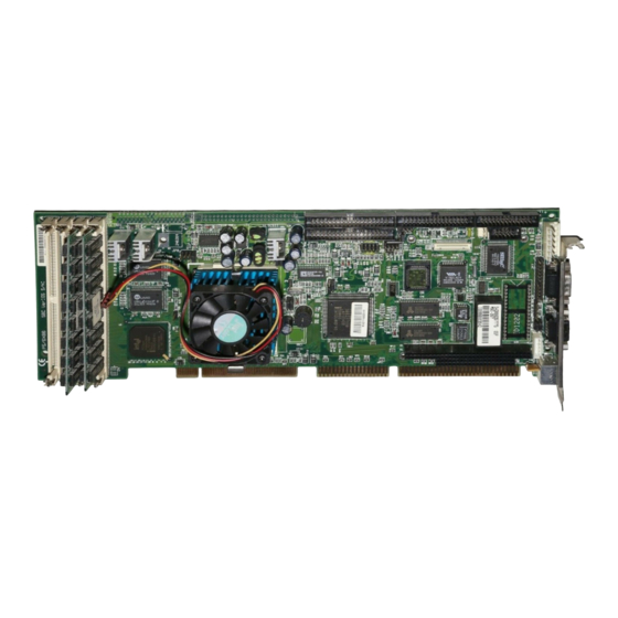
Page 14: Component Locations
Chapter 2 Hardware Configuration 2-2 COMPONENT LOCATIONS COM 1 EXKB 12887 BIOS Pentium 54C/55C 6x86 SIMM 1 SIMM 2 SIMM 3 SIMM 4 PC-550 Connector, Jumper and Component locations ’ Page: 2-3 PC-550 USER S MANUAL... -
Page 15: How To Set Jumpers
PIN1 & PIN2 to create one setting and shorting. You can either connect PIN2 & PIN3 to create another setting. The same jumper diagrams are applied all through this manual. The figure below shows what the manual diagrams look and what they represent. ’ Page: 2-4 PC-550 USER S MANUAL... - Page 16 Chapter 2 Hardware Configuration JUMPER DIAGRAMS JUMPER SETTINGS ’ Page: 2-5 PC-550 USER S MANUAL...
-
Page 17: Cpu Type & Clock Selection
JP8, JP9 : CPU Voltage Selection The jumper settings are as follow : 2-4-1 Intel 75/90 CPU type & clock Jumper setting Jumper Setting (Pin closed) JUMPER TYPE CLOCK ILLUSTRATION 50Mhz Intel Pentium 75Mhz 60Mhz Intel Pentium 90Mhz ’ Page: 2-6 PC-550 USER S MANUAL... -
Page 18: Intel 100/120 Cpu Type & Clock Jumper Setting
Chapter 2 Hardware Configuration 2-4-2 Intel 100/120 CPU type & clock Jumper setting Jumper Setting (Pin closed) JUMPER TYPE CLOCK ILLUSTRATION 66Mhz Intel Pentium 100Mhz 60Mhz Intel Pentium 120Mhz ’ Page: 2-7 PC-550 USER S MANUAL... -
Page 19: Intel 133/150 Cpu Type & Clock Jumper Setting
Chapter 2 Hardware Configuration 2-4-3 Intel 133/150 CPU type & clock Jumper setting Jumper Setting (Pin closed) JUMPER TYPE CLOCK ILLUSTRATION Intel 66Mhz Pentium 133Mhz Intel 60Mhz Pentium 150Mhz ’ Page: 2-8 PC-550 USER S MANUAL... -
Page 20: Intel 166/200 Cpu Type & Clock Jumper Setting
Chapter 2 Hardware Configuration 2-4-4 Intel 166/200 CPU type & clock Jumper Setting Jumper Setting (Pin closed) JUMPER TYPE CLOCK ILLUSTRATION 66Mhz Intel Pentium 166Mhz 66Mhz Intel Pentium 200Mhz ’ Page: 2-9 PC-550 USER S MANUAL... -
Page 21: Intel Mmx-166/200/233 Cpu Type & Clock Jumper Setting
Chapter 2 Hardware Configuration 2-4-5 Intel MMX-166/200/233 CPU type & clock Jumper Setting Jumper Setting (Pin closed) JUMPER TYPE CLOCK ILLUSTRATION 66Mhz Intel Pentium 166Mhz 66Mhz Intel Pentium 200Mhz 66Mhz Intel Pentium 233Mhz ’ Page: 2-10 PC-550 USER S MANUAL... -
Page 22: Cyrix P-120/150/166 Cpu Type & Clock Jumper Setting
Chapter 2 Hardware Configuration 2-4-6 Cyrix P-120/150/166 CPU type & clock Jumper Setting Jumper Setting (Pin closed) JUMPER TYPE CLOCK ILLUSTRATION 50Mhz Cyrix P-120+ 60Mhz Cyrix P-150+ 66Mhz Cyrix P-166+ ’ Page: 2-11 PC-550 USER S MANUAL... -
Page 23: Cyrix Mmx-166/200 Cpu Type & Clock Jumper Setting
Chapter 2 Hardware Configuration 2-4-7 Cyrix MMX-166/200 CPU type & clock Jumper Setting Jumper Setting (Pin closed) JUMPER TYPE CLOCK ILLUSTRATION 60Mhz Cyrix PR-166 66Mhz Cyrix PR-200 ’ Page: 2-12 PC-550 USER S MANUAL... -
Page 24: Cyrix Mmx-233/266 Cpu Type & Clock Jumper Setting
Chapter 2 Hardware Configuration 2-4-8 Cyrix MMX-233/266 CPU type & clock Jumper Setting Jumper Setting (Pin closed) JUMPER TYPE CLOCK ILLUSTRATION 66Mhz Cyrix PR-233 66Mhz Cyrix PR-266 ’ Page: 2-13 PC-550 USER S MANUAL... -
Page 25: Cyrix 6X86L-120/150/166 Cpu Type & Clock Jumper Setting
Chapter 2 Hardware Configuration 2-4-9 Cyrix 6x86L-120/150/166 CPU type & clock Jumper Setting Jumper Setting (Pin closed) JUMPER TYPE CLOCK ILLUSTRATION 50Mhz 6x86L PR-120 60Mhz 6x86L PR-150 66Mhz 6x86L PR-166 ’ Page: 2-14 PC-550 USER S MANUAL... -
Page 26: Amd K5-75/90/100 Cpu Type & Clock Jumper Setting
Chapter 2 Hardware Configuration 2-4-10 AMD K5-75/90/100 CPU type & clock Jumper Setting Jumper Setting (Pin closed) JUMPER TYPE CLOCK ILLUSTRATION 50Mhz K5-75 60Mhz K5-90 66Mhz K5-100 ’ Page: 2-15 PC-550 USER S MANUAL... -
Page 27: Amd K5-120/133/166 Cpu Type & Clock Jumper Setting
Chapter 2 Hardware Configuration 2-4-11 AMD K5-120/133/166 CPU type & clock Jumper Setting Jumper Setting (Pin closed) JUMPER TYPE CLOCK ILLUSTRATION 60Mhz K5-120 66Mhz K5-133 66Mhz K5-166 ’ Page: 2-16 PC-550 USER S MANUAL... -
Page 28: Amd K6-166/200/233 Cpu Type & Clock Jumper Setting
Chapter 2 Hardware Configuration 2-4-12 AMD K6-166/200/233 CPU type & clock Jumper Setting Jumper Setting (Pin closed) JUMPER TYPE CLOCK ILLUSTRATION 66Mhz K6-166 66Mhz K6-200 66Mhz K6-233 ’ Page: 2-17 PC-550 USER S MANUAL... -
Page 29: Rs232/422/485 (Com2) Selection
RS-485 Function Jumper 9-10 9-10 setting 11-12 11-12 (pin closed) 17-18 13-14 19-20 15-16 21-22 17-18 23-24 19-20 21-22 23-24 Jumper illustration 23 24 23 24 23 24 *** Manufactory default --- RS-232. ’ Page: 2-18 PC-550 USER S MANUAL... -
Page 30: At Keyboard Or Ps/2 Mouse Selection
"When BIOS Setup defaults at JP12 SCSI boot-up, and the system equipped with both SSD/SCSI; the system will boot up from SSD. The SCSI device will be default at D Drive. E0000h-E7FFF JP12 ***Manufactory default --- D8000-DFFFF ’ Page: 2-19 PC-550 USER S MANUAL... -
Page 31: Com1 Connector
COM1 : COM1 Connector, DB9 male connector The COM1 Connector assignments are as follow : ASSIGNMENT 2-9 COM2 CONNECTOR COM2 : COM2 Connector The COM2 Connector assignments are as follow : ASSIGNMENT RS-232 RS-422 RS-485 RTS- RTS+ CTS+ CTS- ’ Page: 2-20 PC-550 USER S MANUAL... - Page 32 Chapter 2 Hardware Configuration ’ Page: 2-21 PC-550 USER S MANUAL...
-
Page 33: Keyboard Connector
2-11 EXTERNAL KEYBOARD CONNECTOR EXKB : External Keyboard Connector The pin assignments are as follow : ASSIGNMENT KBCLK KBDATA 2-12 RESET CONNECTOR JP10 : Reset Connector. The pin assignments are as follow : ASSIGNMENT RESET GROUND ’ Page: 2-22 PC-550 USER S MANUAL... -
Page 34: Floppy Disk Drive Connector
34-pin flat cable to attach the FDD on the board, the other side is to attach two FDDs. The pin assignments are as follow : ASSIGNMENT ASSIGNMENT RATE0 INDEX MTR0 DRV1 DRV0 MTR1 STEP WDATA WGATE TRK0 WRPRT RDATA DSKCHG ’ Page: 2-23 PC-550 USER S MANUAL... -
Page 35: Hard Disk Drive Connector
Chapter 2 Hardware Configuration 2-14 HARD DISK DRIVE CONNECTOR IDE1: Hard Disk Drive Connector The PC-550 possesses two HDD connectors, IDE1 and IDE2. The pin assignments are as follow: ASSIGNMENT ASSIGNMENT IDERST IDEREQ0 IDED7 IDEIOW IDED8 IDED6 IDEIOR IDED9 IDED5... - Page 36 IDERST IDEREQ1 IDED7 IDEIOW IDED8 IDED6 IDEIOR IDED9 IDED5 IDERDY IDED10 PULL HI IDED4 IDEACK1 IDED11 IDED3 IDESIRQ IDED12 IOCS16 IDED2 IDEA1 IDED13 IDED1 IDEA0 IDED14 IDEA2 IDED0 IDECS1S IDED15 IDECS3S IDELEDS N.C. ’ Page: 2-25 PC-550 USER S MANUAL...
-
Page 37: Hard Disk Drive Led Connector
2-17 PANEL INVERTER DELAY-POWER CONNECTOR JP11 : Panel Inverter Delay-power Connector This Connector acts as an inverter to supply proper power to panel LCD. The pin assignments are as follow : ASSIGNMENT LCD+12V LCD VDD(+5V) ’ Page: 2-26 PC-550 USER S MANUAL... -
Page 38: Lcd Panel Connector
LCD : LCD Panel Connector The connector LCD is a 41-pin, dual-in-line header used for Flat Panel displays. The pin assignments are as follow : ASSIGNMENT ASSIGNMENT SHFCLK 3.3V 3.3V ENABKL LCDVDD ENVEE +12V +12V ’ Page: 2-27 PC-550 USER S MANUAL... -
Page 39: Vga Crt Connector
VGA : VGA CRT Connector The pin assignments are as follow: ASSIGNMENT ASSIGNMENT GREEN BLUE HSYNC VSYNC 2-20 POWER CONNECTOR PWR : Power Connector The pin assignments are as follow : ASSIGNMENT +12V -12V ’ Page: 2-28 PC-550 USER S MANUAL... -
Page 40: Printer Connector
As to link the Printer to the card, you need a cable to connect both DB25 connector and parallel port. The pin assignments are as follow : ASSIGNMENT ASSIGNMENT AUTFE ERROR INIT SLCTIN BUSY SLCT ’ Page: 2-29 PC-550 USER S MANUAL... -
Page 41: External Speaker Connector
2-23 SCSI CONNECTOR SCSI1, ULTRA1 : SCSI Connector The PC-550 equips with two SCSI Connectors on board, SCSI1 and SCSI 2. The SCSI 1 is a 50 pins dual-in-line header, SCSI2 is a 68 pins dual- in-line header.The pin assignments are as follow :... - Page 42 PCI Bus Master is occupied. The SCSI Bus Master (DRQ3) is same as 4 PCI Slot on the backplane (DRQ3). When SCSI chipset is on-board, the 4 PCI Slot on the backplane would fail even if SCSI function is disabled . ’ Page: 2-31 PC-550 USER S MANUAL...
-
Page 43: Memory Installation
Chapter 2 Hardware Configuration 2-24. MEMORY INSTALLATION The PC-550 P5/6x86 Pentium Embedded Card support 4 DRAM banks ,bank 0 and bank 1 in four pieces 72 pin SIMM sockets on board. SIMM 1,2,3,4 for double Bank DRAM module Note: (72pin x 32bit x 4) -
Page 44: Solid State Disk Socket
Chapter 2 Hardware Configuration 2-25. SOLID-STATE DISK SOCKET SSD: 32-pin Disk-on-chip Socket The pin assignments are as follows: ASSIGNMENT ASSIGNMENT SA12 SA10 SA11 ’ Page: 2-33 PC-550 USER S MANUAL... -
Page 45: Universal Serial Bus Connector
Chapter 2 Hardware Configuration 2-26 UNIVERSAL SERIAL BUS CONNECTOR USB: Universal Serial Bus Connector The pin assignments are as follows: ASSIGNMENT USBP∅− USBP∅+ USBP1− USBP1+ ’ Page: 2-34 PC-550 USER S MANUAL... - Page 46 Chapter 2 Hardware Configuration ’ Page: 2-35 PC-550 USER S MANUAL...
-
Page 47: Chapter 3 Software Utilities
CHAPTER SOFTWARE UTILITIES This chapter comprises the detailed information of VGA driver, SCSI driver. It also describe on how to update BIOS and on how to configure watchdog timer. Section includes: ! VGA Driver Utility ! Flash BIOS Update ! SCSI Driver Utility ! Watchdog Timer Configuration Page: 3-1... -
Page 48: Introduction
Chapter 3 Software Configuration 3-1. INTRODUCTION Enclosed with our PC-550 package is our driver utility, which may comes in a form of a CD ROM disc or floppy diskettes. For CD ROM disc user, you will only need some of the files contained in the CD ROM disc, please kindly... - Page 49 PROPERTIES window, then choose the SETTING tab, then DISPLAY TYPE. (3). In the CHANGE DISPLAY TYPE window, click on the CHANGE button in the ADAPTER TYPE, this will bring up the SELECT DEVICE window. PC-550 USER ′ S MANUAL Page:3-3...
- Page 50 (vii) When the Display Driver Install window appears, select PRIMARY DISPLAY, and click OK. (viii) When the Primary Display Driver List window appears, select “Chips and Technologies 65550” from the list of Adapter types, then select OK to install the video driver. PC-550 USER ′ S MANUAL Page:3-4...
-
Page 51: Flash Bios Update
Disk for update of system BIOS and VGA BIOS. 3-3-2. To update VGA BIOS for LCD Flat Panel Display: As PC-550 user, You have to update the VGA BIOS for the specific LCD flat panel, you are going to use. In doing this, you need two files. - Page 52 BIOS, do not turn off or reset the system, or you will damage the BIOS. After you have completed all the programming, you will see the line: “Programming Flash Memory ok”. Please power off or reset the system. Then the Flash BIOS is fully implemented. PC-550 USER ′ S MANUAL Page:3-6...
-
Page 53: Scsi Driver Utility
Chapter 3 Software Configuration 3-4. SCSI DRIVER UTILITY 3-4-1. Introduction PC-550 is embedded with SCSI Adaptec 7880 can support SCSI II and Ultra-wide SCSI. Installation programs are provided as follows: 1. Netware program 2. OS/2 program 3. Windows 3.1 / 9x / NT 4. -
Page 54: Watchdog Timer Configuration
I/O port 441H , the system will run the command to stop the Watchdog function. The PC-550 watchdog function, You must write your program so when it writes I/O port address 443 for enable watchdog and write I/O port address 441 for disable watchdog. -
Page 55: Chapter 4 Green Pc Function
CHAPTER GREEN PC FUNCTION This chapter gives you the concise information for Green PC Function. Section includes: ! Power Saving Block Diagram ! CPU Doze Mode ! System STANDBY Mode ! System SUSPEND Mode Page: 4-1... -
Page 56: Power Saving Block Diagram
4. Level 1 cache are disabled. 5. VGA monitor displays blank screen. 6. Fixed disk driver motor will be spin off. 7. Any activity occurs, system will exit from Standby mode to On mode. PC-550 USER ′ S MANUAL Page: 4-2... -
Page 57: System Suspend Mode
6. Fixed disk driver motor will be spin off. 7. Monitor activity according to the setting of Advanced Setup. 8. When system in Suspend mode, only Keyboard / Mouse / Alarm resume can wakeup system. PC-550 USER ′ S MANUAL Page: 4-3... - Page 58 Chapter 4 Green PC Function PC-550 USER ′ S MANUAL Page: 4-4...
-
Page 59: Chapter 5 Award Bios Setup
CHAPTER AWARD BIOS SETUP This chapter states out how to set up the Award BIOS. Section includes: ! Introduction ! Entering Setup ! The Standard CMOS Setup ! The BIOS Features Setup ! The Chipset Features Setup ! Power Management Setup ! PNP/PCI Configuration ! Load BIOS defaults ! Integrated Peripherals... -
Page 60: Introduction
5-1. INTRODUCTION This chapter will show you the function of BIOS in managing the features of your system. The PC-550 Pentium Embedded Card is equipped with the BIOS for system chipset from Award Software Inc. This page briefly explains the function of BIOS in managing the special features of your system. -
Page 61: Entering Setup
LOAD BIOS DEFAULTS EXIT WITHOUT SAVING LOAD SETUP DEFAULTS ↑↓→← Esc : Quit :SELECT ITEM F10 : Save & Exit Setup (Shift)F2 : Change Color Time, Date, Hard Disk Type..Setup program initial screen PC-550 USER ′ S MANUAL Page: 5-3... -
Page 62: The Standard Cmos Setup Menu
Since you have not yet set the time and date, the date displayed is probably incorrect. Information on each item is PC-550 USER ′ S MANUAL Page: 5-4... - Page 63 If the controller of HDD interface is ESDI, the selection shall be "Type 1". If the controller of HDD interface is SCSI, the selection shall be "None" If the controller of HDD interface is CD-ROM, the selection shall be "None" PC-550 USER ′ S MANUAL Page: 5-5...
- Page 64 The option are 360KB 5.25in, 1.2KB 5.25in, 720KB 3.5in, 1.44MB 3.5in, 2.88MB 3.5in and None. Not Installed could be used as an option for diskless workstations. VIDEO: Options are Monochrome, Color 40, VGA/EGA, Color 80. PC-550 USER ′ S MANUAL Page: 5-6...
- Page 65 1024 65535 1023 1024 65535 1023 1024 65535 1023 1024 65535 1023 1024 65535 1023 65535 1023 65535 1024 65535 1023 1024 65535 1023 65535 65535 65335 AUTO Award Hard Disk Type Table PC-550 USER ′ S MANUAL Page: 5-7...
-
Page 66: The Bios Features Setup Menu
F1 key. A Windows will appear on your screen detailing the various options available for each item. A brief introduction of each setting in the BIOS FEATURES SETUP program is given below. PC-550 USER ′ S MANUAL Page: 5-8... - Page 67 BIOS encounters a parity error it will be ignored. We re-commend that you always enable the item in order to ensure that the memory is good each time you turn your PC on. PC-550 USER ′ S MANUAL Page: 5-9...
- Page 68 Do not type anything and just press <Enter>, it will disable security. Once the security is disabled, the system will boot and you can enter Setup freely. PC-550 USER ′ S MANUAL Page: 5-10...
-
Page 69: Chipset Features Setup
Set this option to Disabled to manually set DRAM, cache and I/O bus clock operating parameters. DRAM Mode: The number of wait states added on reads to DRAM. Fewer wait states improve performance. PC-550 USER ′ S MANUAL Page: 5-11... -
Page 70: Power Management Setup
This category determines how much power consumption for system after selecting below items. Default value is Disable. Having made all the settings above, press < Esc > to return to the main menu. PC-550 USER ′ S MANUAL Page: 5-12... - Page 71 STANDBY mode. This options as following: From 30 Sec to 2 Hours or Disabled. SUSPEND MODE TIMER: Sets the time interval after system inactivity when the system enters SUSPEND mode. This options as following: From 30 Sec to 2 Hours or Disabled. PC-550 USER ′ S MANUAL Page: 5-13...
-
Page 72: Pnp/Pci Configuration
<F1> key, the all options for the desired selection will be displayed for choice. User has to use select the desired options. Having made all the above setting according to your configuration. Press <Esc> to return to the main menu. PC-550 USER ′ S MANUAL Page: 5-14... -
Page 73: Load Bios Defaults
Load BIOS Default ( Y / N ) ? Y To use the BIOS defaults, change the prompt to "Y" and press < Enter >, the CMOS is load automatically when you power on the PC-550. 5-9 LOAD SETUP DEFAULTS AUTO CONFIGURATION WITH SETUP DEFAULTS This Main Menu item uses the default SETUP values. -
Page 74: Integrated Peripherals
User has to use select the desired option. Having made all the setting according to your selections. Press <Esc> to return to the Main Menu. PC-550 USER ′ S MANUAL Page: 5-16... -
Page 75: Password Setting
Setup. If you select Setup at Security Option of BIOS Features Setup Menu, you will be prompted only when you try to enter Setup. PC-550 USER ′ S MANUAL Page: 5-17... -
Page 76: Ide Hdd Auto Detection
If HDD does not support LBA mode, ‘LBA’ option will be shown. If no of cylinders is less then or equal to 1024, no ‘LARGE’ option will be shown. User can select a mode which is appropriate for then. PC-550 USER ′ S MANUAL Page: 5-18... - Page 77 The maximum HDD size supported by LBA mode is 8.4 Gigabyte which is obtained by the following formula: no. Cylinder (1024) x no. Head ( 255) x no. Sector ( 63) x no. Per sector ( 512) --------------------------------------- Total: 8.4 Giga byte PC-550 USER ′ S MANUAL Page: 5-19...
- Page 78 All these softwares are located in the Award HDD Service Routine (INT 13h). It may be failed to access a HDD with LBA(LARGE) mode selected if you are running under a Operating System which replaces the whole INT 13h. PC-550 USER ′ S MANUAL Page: 5-20...
-
Page 79: Hdd Low Level Format
User has to use select the desired option. Having made all the setting according to your selections. Press <Esc> to return to the Main Menu. PC-550 USER ′ S MANUAL Page: 5-21... -
Page 80: Save & Exit Setup
You may call up the setup program at any time to adjust any of the individual items by pressing the <Del> key during boot up. PC-550 USER ′ S MANUAL Page: 5-22... - Page 81 Quit Without Saving (Y/N) ? Y LOAD BIOS DE SAVING LOAD SETUP DEFAULTS ↑↓→← Esc : Quit :SELECT ITEM F10 : Save & Exit Setup (Shift)F2 : Change Color Abandon all Datas & Exit SETUP PC-550 USER ′ S MANUAL Page: 5-23...
- Page 82 Chapter 5 Award BIOS Setup PC-550 USER ′ S MANUAL Page: 5-24...
-
Page 83: Appendix A Expansion Bus
APPENDIX EXPANSION BUS This appendix indicates you the pin assignments. Section includes: ! PC-104 Connector Pin Assignment ! ISA BUS Pin Assignment ! PCI BUS Pin Assignment Page: A-1... - Page 84 IRQ15 LA18 IRQ14 +12V LA17 DACK0 IOCHRDY MEMR DRQ0 SMEMW MEMW DACK5 SMEMR DRQ5 DACK6 DRQ6 DACK3 DACK7 DRQ3 DRQ7 DACK1 DRQ1 MASTER REFRESH KEY PIN IRQ7 IRQ6 IRQ5 IRQ4 IRQ3 DACK2 BALE PC-550 USER ′ S MANUAL Page: A-2...
- Page 85 SD12 -DRQ3 SA15 SD13 -DACK1 SA14 -MASTER SD14 -DRQ1 SA13 SD15 -REFRESH SA12 BCLK SA11 IRQ7 SA10 IRQ6 SA09 IRQ5 SA08 IRQ4 SA07 IRQ3 SA06 -DACK2 SA05 SA04 BALE SA03 SA02 SA01 SA00 PC-550 USER ′ S MANUAL Page: A-3...
-
Page 86: Pci Bus Pin Assignment
AD30 AD08 C/BE0# AD29 +3.3V AD07 +3.3V AD28 +3.3V AD06 AD27 AD26 AD05 AD04 AD25 AD03 +3.3V AD24 AD02 C/BE3# GNT2# AD01 AD00 AD23 +3.3V +5V(I/O) +5V(I/O) AD22 ACK64# REQ64# AD21 AD20 AD19 PC-550 USER ′ S MANUAL Page: A-4... - Page 87 APPENDIX TECHNICAL SUMMARY This section introduce you the maps concisely. Section includes: ! Interrupt Map ! RTC & CMOS RAM Map ! Timer & DMA Channels Map ! I / O & Memory Map Page: B-1...
-
Page 88: Appendix B Technical Summary Interrupt Map
Keyboard output buffer full Cascade for IRQ 8-15 Serial port 2 Serial port 1 Available Floppy Disk adapter Parallel port 1 RTC clock Available Available Available Available Math coprocessor Hard Disk adapter Available PC-550 USER ′ S MANUAL Page: B-2... -
Page 89: Rtc & Cmos Ram Map
Extension memory low byte Extension memory high byte Reserved for extension memory low byte Reserved for extension memory high byte Date Century byte Information Flag 34-3F Reserve 40-7f Reserved for Chipset Setting Data PC-550 USER ′ S MANUAL Page: B-3... -
Page 90: Timer & Dma Channels Map
Assignment System timer interrupt DRAM Refresh request Speaker tone generator DMA Channel Map : DMA Channel Assignment Available IBM SDLC Floppy Disk adapter Channel-3 Available Cascade for DMA controller 1 Available Available Available PC-550 USER ′ S MANUAL Page: B-4... -
Page 91: I/O & Memory Map
Parallel port-2 2B0-2DF Graphics adapter controller 2F8-2FF Serial port-2 360-36F Net work ports 378-37F Parallel port-1 3B0-3BF Monochrome & Printer adapter 3C0-3CF EGA adapter 3D0-3DF CGA adapter 3F0-3F7 Floppy disk controller 3F8-3FF Serial port-1 PC-550 USER ′ S MANUAL Page: B-5... - Page 92 Appendix B Technical Summary PC-550 USER ′ S MANUAL Page: B-6...
-
Page 93: Appendix C Trouble Shooting
APPENDIX TROUBLE SHOOTING This section outlines the error messages that may occur when you operate the system. It also gives you the suggestions on solving the problems. Section includes: ! Trouble Shooting for Error Messages ! Trouble Shooting for POST Code Page: C-1... - Page 94 When you can‘t find the boot device, insert a system disk into Drive A and press < Enter >. Make sure both the controller and cables are all in proper positions, also make sure the disk is formatted correct device. Then reboot the system. PC-550 USER ′ S MANUAL Page: C-2...
- Page 95 Memory has been added or removed since the last boot. In EISA mode use Configuration Utility to re-configure the memory configuration. In ISA mode enter Setup and enter the new memory size in the memory fields. PC-550 USER ′ S MANUAL Page: C-3...
- Page 96 03 : Initialize all the standard devices with default values Standard devices includes : DMA controller (8237). Programmable Interrupt Controller (8259). Programmable Interval Timer (8254). RTC chip. 05 : 1.Keyboard Controller Self-Test. 2.Enable Keyboard Interface. 07 : Verfies CMOS‘s basic R/W functionality. PC-550 USER ′ S MANUAL Page: C-4...
- Page 97 0D : 1. Program some of the Chipset‘s value according to Setup. (Early Setup Value Program). 2. Measure CPU speed for display & decide the system clock speed. 3. Video initialization including Monochrome ,CGA, EGA/VGA. If no display device found, the speaker will beep. PC-550 USER ′ S MANUAL Page: C-5...
- Page 98 2.Program all onboard super I/O chips (if any) including COM ports, LPT ports, FDD port..according to setup value. 3C : Set flag to allow users to enter CMOS Setup Utility. 3D : 1 Initialize Keyboard. 2 Install PS2 mouse. PC-550 USER ′ S MANUAL Page: C-6...
- Page 99 -assign I/O, Memory, IRQ & DMA TO PnP ISA devices. -initialize all PnP ISA ROMs. 4. Program shadows RAM according to Setup settings. 5. Program parity according to Setup setting. 6. Power Management Initialization. -Enable/Disable global PM. -APM interface initialization. PC-550 USER ′ S MANUAL Page: C-7...
- Page 100 (PnP BIOS only). 2. Clear memory that have been used. 3. Boot system via INT 19H. FF : System Booting. this means that the BIOS already pass the control right to the operating system. PC-550 USER ′ S MANUAL Page: C-8...
- Page 101 Appendix C Trouble Shooting PC-550 USER ′ S MANUAL Page: C-9...
- Page 102 Appendix C Trouble Shooting PC-550 USER ′ S MANUAL Page: C-10...
- Page 103 Appendix C Trouble Shooting PC-550 USER ′ S MANUAL Page: C-11...
- Page 104 Appendix C Trouble Shooting PC-550 USER ′ S MANUAL Page: C-12...
- Page 105 Appendix C Trouble Shooting PC-550 USER ′ S MANUAL Page: C-13...
- Page 106 Appendix C Trouble Shooting PRINTED IN TAIWAN PC-550 USER ′ S MANUAL Page: C-14...
Need help?
Do you have a question about the PC-550 and is the answer not in the manual?
Questions and answers