Table of Contents
Advertisement
Advertisement
Table of Contents
Troubleshooting

Subscribe to Our Youtube Channel
Related Manuals for protech ProX-1630


Summary of Contents for protech ProX-1630
- Page 1 USER’S MANUAL...
- Page 2 Copyright Notice ProX-1630 Socket 370 Half-sized Embedded Card With VGA / LAN OPERATION MANUAL COPYRIGHT NOTICE This operation manual is meant to assist both Embedded Computer manu- facturers and end-users in installing and setting up the system. The infor- mation contained in this document is subject to change without any prior notice.
-
Page 3: Table Of Contents
Contents TABLE OF CONTENTS CHAPTER 1 INTRODUCTION About This Manual ............System Specifications ........... Safety Precautions ............CHAPTER 2 HARDWARE CONFIGURATION Jumper & Connector Quick Reference Table ....Component Locations ........... How to Set the Jumpers ..........COM Port Connector ............ RS232/422/485 (COM2) Selection ....... - Page 4 Contents CHAPTER 3 SOFTWARE UTILITIES Introduction ..............VGA Driver Utility ............Flash BIOS Update ............LAN Drivers Utilities ............ Watchdog Timer Configuration ........CHAPTER 4 GREEN PC FUNCTION Power Saving Block Diagram ........CPU Doze Mode ............System Standby Mode ..........System Suspend Mode ..........
- Page 5 Contents RTC & CMOS RAM Map ............Timer & DMA Channels Map ..........I/O & Memory Map ..............APPENDIX C TROUBLE SHOOTING Trouble Shooting for Error Messages ........Trouble Shooting for POST Codes ..........
-
Page 6: Chapter 1 Introduction
CHAPTER INTRODUCTION This chapter gives you the information for Prox-1630. It also outlines the System specifications. Section includes: About This Manual System Specifications Safety precautions Experienced users can skip to chapter 2 on page 2-1 for a Quick Start. Page:1-1... -
Page 7: About This Manual
1-1. ABOUT THIS MANUAL Thank you for purchasing our Prox-1630 Socket 370 Half-sized Embedded Card with VGA/LAN, which is fully PC / AT compatible. The Prox-1630 provides faster processing speed, greater expandability and can handle more tasks than before. This manual is designed to assist you how to install and set up the system. -
Page 8: System Specifications
Mini DIN connector, support AT Keyboard or PS/2 Mouse by jumper selection. One additional 5-pin External keyboard connector. ! ! ! ! BUS SUPPORT : External ISA. Internal PCI Bus for VGA, LAN, & IDE. Prox-1630 USER ′ S MANUAL Page: 1-3... - Page 9 A 32-pin SSD socket on board, supports up to 144MB Disk-on-chips. USB CONNECTOR : Universal Serial Bus Connector on board, supports up to two USB ports. LAN ADAPTER : MXIC MX98715 Fast Ethernet 10/100 Base-T PCI-BUS Prox-1630 USER ′ S MANUAL Page: 1-4...
- Page 10 INTERRUPT LEVELS : OPERATING TEMPERATURE : 0 to 60°C. SYSTEM POWER REQUIREMENT : DC Voltage: +5V, minimum +4.75V, maximum 5.25V. DC Ampere: 15A. DC Voltage: +12V, minimum +11.4V, maximum 12.6V. DC Ampere: 500mA. Prox-1630 USER ′ S MANUAL Page: 1-5...
-
Page 11: Safety Precautions
3. Disconnect power when you change any hardware devices. For instance, when you connect a jumper or install any cards, a surge of power may damage the electronic components or the whole system. Prox-1630 USER ′ S MANUAL Page: 1-6... -
Page 12: Chapter 2 Hardware Configuration
CHAPTER HARDWARE CONFIGURATION ** QUICK START ** Helpful information describes the jumper & connector settings, and component locations. This section includes: Jumper & Connector Quick Reference Table Component Locations Configuration and Jumper settings Connector‘s Pin Assignments Page 2-1... -
Page 13: Jumper & Connector Quick Reference Table
Universal Serial Bus Connector ......LAN Connector ............. Solid-State Disk Socket ......... Panel VCC Selection ..........Green Function Connector ........LAN LED Indicator ..........LED1, LED2 IRQ 12 Release Selection ……………………….. DIMM1 Memory Installation ..........’ Page: 2-2 Prox-1630 USER S MANUAL... -
Page 14: Component Locations
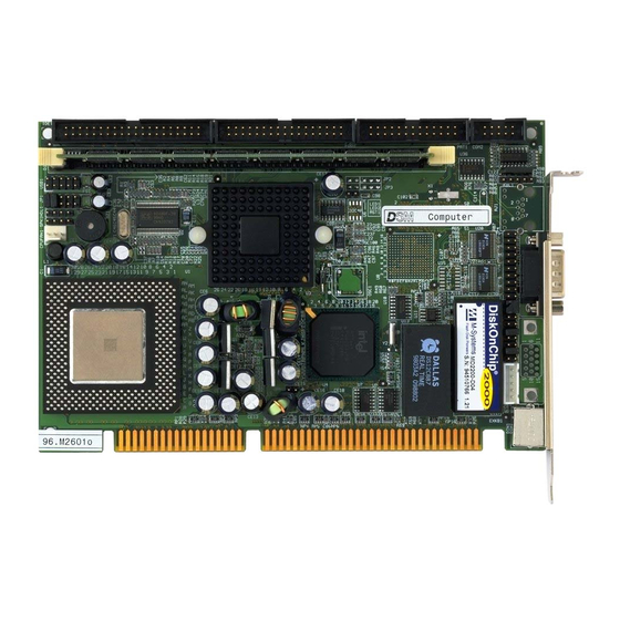
Chapter 2 Hardware Configuration 2-2. COMPONENT LOCATIONS COM 1 EXKB 12887 Prox-1630 Connector, Jumper and Component locations ’ Page: 2-3 Prox-1630 USER S MANUAL... -
Page 15: How To Set The Jumpers
PIN2 & PIN3 to create another setting. The same jumper diagrams are applied all through this manual. The figure below shows what the manual diagram looks like and what they represent. ’ Page: 2-4 Prox-1630 USER S MANUAL... - Page 16 Chapter 2 Hardware Configuration JUMPER DIAGRAMS JUMPER SETTINGS ’ Page: 2-5 Prox-1630 USER S MANUAL...
-
Page 17: Com Port Connector
COM1 : COM1 Connector, DB9 male connector The COM1 Connector assignments are as follows : ASSIGNMENT COM2 : COM2 Connector The COM2 Connector assignments are as follows : ASSIGNMENT RS-232 RS-422 RS-485 RTS- RTS+ CTS+ CTS- ’ Page: 2-6 Prox-1630 USER S MANUAL... -
Page 18: Rs232/422/485 (Com2) Selection
The jumper settings are as follows : COM 2 RS-232 RS-422 RS-485 Function Open Jumper 9-10 9-10 setting 11-12 11-12 (pin closed) 13-14 13-14 15-16 15-16 17-18 17-18 19-20 19-20 Jumper illustration *** Manufactory default --- RS-232. ’ Page: 2-7 Prox-1630 USER S MANUAL... -
Page 19: Ssd Memory Mapping Selection
Flash ROM SSD can be install as one of user’s hard disk drive. The SSD Memory Mapping are as follows: JUMPER SETTINGS SSD Memory Map JUMPER (pins closed) ILLUSTRATION CC000h-CDFFFh D0000h-D1FFFh D4000h-D5FFFh D8000h-D9FFFh DC000h-DDFFFh E0000h-E1FFFh *** Manufactory default --- CC000h-CDFFFh ’ Page: 2-8 Prox-1630 USER S MANUAL... -
Page 20: Keyboard Or Ps/2 Mouse Selection
DIN : PC/AT Keyboard or PS/2 Mouse Connector DIN connector can support PC/AT Keyboard or PS/2 Mouse. The pin assignments are as follows : ASSIGNMENT KEYBOARD PS/2 MOUSE KBDATA MOUSE DATA KBCLK MSCLK ’ Page: 2-9 Prox-1630 USER S MANUAL... -
Page 21: External Keyboard Connector
ASSIGNMENT RESET GROUND 2-11. HARD DISK DRIVE LED CONNECTOR HDL : Hard Disk Drive LED Connector The pin assignments are as follows : ASSIGNMENT HDD Active Signal HDD Active Signal HDD Active Signal ’ Page: 2-10 Prox-1630 USER S MANUAL... -
Page 22: Vga Crt Connector
Chapter 2 Hardware Configuration 2-12. VGA CRT CONNECTOR VGA : VGA CRT Connector The pin assignments are as follows: ASSIGNMENT GREEN BLUE HSYNC VSYNC ’ Page: 2-11 Prox-1630 USER S MANUAL... -
Page 23: Cpu Fan Connector
Speaker Signal Speaker Signal Speaker Signal 2-15. POWER LED & KEYLOCK CONNECTOR KBL : Power LED & Keylock Connector The pin assignments are as follows : ASSIGNMENT Power LED Ground Keyboard INT Ground ’ Page: 2-12 Prox-1630 USER S MANUAL... -
Page 24: Floppy Disk Drive Connector
34-pin flat cable to attach the FDD on the board, the other side attaches to two FDDs. The pin assignments are as follows : ASSIGNMENT ASSIGNMENT INDEX MTR0 DRV1 DRV0 MTR1 STEP WDATA WGATE TRK0 WRPRT RDATA DSKCHG ’ Page: 2-13 Prox-1630 USER S MANUAL... -
Page 25: Hard Disk Drive Connector
IDERST IDEREQ0 IDED7 IDEIOW IDED8 IDED6 IDEIOR IDED9 IDED5 IDERDY IDED10 PULL HI IDED4 IDEACK0 IDED11 IDED3 IRQ14 IDED12 IOCS16 IDED2 IDEA1 IDED13 IDED1 IDEA0 IDED14 IDEA2 IDED0 IDECS1P IDED15 IDECS3P IDELEDP N.C. ’ Page: 2-14 Prox-1630 USER S MANUAL... -
Page 26: Lcd Panel Connector
LCD : LCD Panel Connector The connector LCD is a 51-pin, dual-in-line header used for Flat Panel displays. The pin assignments are as follows : ASSIGNMENT ASSIGNMENT LCD VDD LCDVDD VDDSAFE VDDSAFE ENABKL SHFCLK ENVEE 12VSAFE 12VSAFE ’ Page: 2-15 Prox-1630 USER S MANUAL... -
Page 27: Printer Connector
As to link the Printer to the card, you need a cable to connect both DB25 connector and parallel port. The pin assignments are as follows : ASSIGNMENT ASSIGNMENT AUTFE ERROR INIT SLCTIN BUSY SLCT ’ Page: 2-16 Prox-1630 USER S MANUAL... -
Page 28: Universal Serial Bus Connector
USB connector of this board can support two USB ports. The pin assignments are as follows: ASSIGNMENT USBP∅− USBP∅+ USBP1− USBP1+ 2-21. LAN CONNECTOR UTP: LAN Connector The pin assignments are as follows: ASSIGNMENT ISOLATED GND ISOLATED GND ISOLATED GND ISOLATED GND ’ Page: 2-17 Prox-1630 USER S MANUAL... - Page 29 Chapter 2 Hardware Configuration 2-22. SOLID-STATE DISK SOCKET SSD: 32-pin Disk-on-chip Socket The pin assignments are as follows: ASSIGNMENT ASSIGNMENT SA12 SA10 SA11 ’ Page: 2-18 Prox-1630 USER S MANUAL...
-
Page 30: Panel Vcc Selection
JP2: Panel VCC Selection The pin assignments are as follows: Panel VCC Selection JUMPER SETTINGS JUMPER (pins closed) ILLUSTRATION VCC3.3V 2-24. GREEN FUNCTION CONNECTOR GRN: Green Function Connector The pin assignments are as follows: ASSIGNMENT EXTSMI- ’ Page: 2-19 Prox-1630 USER S MANUAL... -
Page 31: Lan Led Indicator
Chapter 2 Hardware Configuration 2-25. LAN LED INDICATOR Prox-1630 possesses 2 LAN Led Indicators, namely: LED1, and LED2. The pin assignments are as follows: LED1: LAN Led Indicator This Led indicator is used to detect data transfer. ASSIGNMENT Pull Hi... -
Page 32: Memory Installation
Chapter 2 Hardware Configuration 2-27. MEMORY INSTALLATION The Prox-1630 Embedded Computer support 1 SDRAM banks. DRAM BANK CONFIGURATION DIMM 1 TOTAL MEMORY 128M 128M 256M 256M ’ Page: 2-21 Prox-1630 USER S MANUAL... - Page 33 Chapter 2 Hardware Configuration ’ Page: 2-22 Prox-1630 USER S MANUAL...
-
Page 34: Chapter 3 Software Utilities
CHAPTER SOFTWARE UTILITIES This chapter comprises the detailed information of VGA driver, LAN driver and flash BIOS update. It also describes on how to install the watchdog timer. Section includes: VGA Driver Utilities Flash BIOS Update LAN Driver Utilities Watchdog Timer Configuration Page: 3-1... -
Page 35: Introduction
Chapter 3 Software Configuration 3-1. INTRODUCTION Enclosed with our Prox-1630 package is our driver utilities, which may comes in a form of a CD ROM disc or floppy diskettes. For CD ROM disc user, you will only need some of the files contained in the CD ROM... - Page 36 PROPERTIES window, then choose the SETTING tab, then DISPLAY TYPE. (3). In the CHANGE DISPLAY TYPE window, click on the CHANGE button in the ADAPTER TYPE, this will bring up the SELECT DEVICE window. Prox-1630 USER ′ S MANUAL Page:3-3...
- Page 37 (vii) When the Display Driver Install window appears, select PRIMARY DISPLAY, and click OK. (viii) When the Primary Display Driver List window appears, select “Chips and Technologies 69000” from the list of Adapter types, then select OK to install the video driver. Prox-1630 USER ′ S MANUAL Page:3-4...
-
Page 38: Flash Bios Update
Utility Disk for system BIOS and VGA BIOS update. 3-3-2. To update VGA BIOS for LCD Flat Panel Display: As Prox-1630 user, you have to update the VGA BIOS for your specific LCD flat panel you are going to use. For doing this, you need two files. - Page 39 File Name to Program: 630xxxxx.bin Checksum: XXXXX Reset System or Power off to accomplish update process! F1: Reset F10: Exit Please reset or power off the system, then the Flash BIOS is fully implemented. Prox-1630 USER ′ S MANUAL Page:3-6...
-
Page 40: Lan Drivers Utilities
Chapter 3 Software Configuration 3-4. LAN DRIVERS UTILITES 3-4-1. Introduction Prox-1630 Embedded Board is enhanced with LAN function can support various network adapters. Installation programs for LAN drivers are listed as follows: 3-4-2. Installing Driver Procedure on Microsoft Windows 95/98 1. - Page 41 8. To complete network installation, remember binding the adapter to transport drivers by choosing “OK” button under Network Setting dialog box. 9. Restart your systems. For more details on Installation procedure. please refer to Readme.txt file found on LAN DRIVER UTILITY. Prox-1630 USER ′ S MANUAL Page:3-8...
-
Page 42: Watchdog Timer Configuration
I/O port 0441H, the system will run the command to stop the Watchdog function. The Prox-1630 watchdog function, You must write your program so when it writes I/O port address 0443 for enable watchdog and write I/O port address 0441 for disable watchdog. - Page 43 Chapter 3 Software Configuration Prox-1630 USER ′ S MANUAL Page:3-10...
-
Page 44: Chapter 4 Green Pc Function
CHAPTER GREEN PC FUNCTION This chapter gives you the concise information for Green PC Function. Sections include: Power Saving Block Diagram CPU Doze Mode System STANDBY Mode System SUSPEND Mode Page: 4-1... -
Page 45: Power Saving Block Diagram
3. Level 1 cache are disabled. 4. VGA monitor displays blank screen. 5. Fixed disk driver motor will be spin off. 6. Any activity occurs, system will exit from Standby mode to On mode. Prox-1630 USER ′ S MANUAL Page: 4-2... -
Page 46: System Suspend Mode
6. Fixed disk driver motor will be spin off. 7. Monitor activity according to the setting of Advanced Setup. 8. When system in Suspend mode, only Keyboard / Mouse / Alarm resume can wakeup system. Prox-1630 USER ′ S MANUAL Page: 4-3... - Page 47 Chapter 4 Green PC Function Prox-1630 USER ′ S MANUAL Page: 4-4...
-
Page 48: Chapter 5 Award Bios Setup
CHAPTER AWARD BIOS SETUP This chapter shows how to set up the Award BIOS. Section includes: Introduction Entering Setup The Standard CMOS Setup The BIOS Features Setup The Chipset Features Setup Power Management Setup PNP/PCI Configuration Load BIOS/Setup defaults Integrated Peripherals IDE HDD Auto Detection Save and Exit Setup Page: 5-1... -
Page 49: Introduction
5-1. INTRODUCTION This chapter will show you the function of a BIOS in managing the features of your system. The Prox-1630 Celeron Socket 370 Embedded Card is equipped with the BIOS for system chipset from Award Software Inc. This page briefly explains the function of a BIOS in managing the special features of your system. -
Page 50: Entering Setup
As you highlight each item, a brief description of that item's function appears in the lower window. If you have a color monitor you can use the Shift F2 keys to scroll through the various color combinations available. Prox-1630 USER ′ S MANUAL Page: 5-3... -
Page 51: The Standard Cmos Setup Menu
< Hour >, < Minute >, and < Second >. Use 24 hour clock format, i.e., for PM numbers, add 12 to the hour. For example, 4: 30 P.M. You should enter the time as 16:30:00. Prox-1630 USER ′ S MANUAL Page: 5-4... - Page 52 Precomp is the read delay circuitry which takes into account the timing differences between the inner and outer edges of the surface of the disk platter. The number designates the starting cylinder of the signal. Prox-1630 USER ′ S MANUAL Page: 5-5...
- Page 53 This category allows user to choose whether the computer will stop if an error is detected during power up. Available options are “All errors”, “No errors”, “All, But keyboard”, “All, But Diskette”, and “All But Disk/Key”. Prox-1630 USER ′ S MANUAL Page: 5-6...
- Page 54 1024 65535 1023 1024 65535 1023 1024 65535 1023 1024 65535 1023 1024 65535 1023 65535 1023 65535 1024 65535 1023 1024 65535 1023 65535 65535 65335 AUTO Award Hard Disk Type Table Prox-1630 USER ′ S MANUAL Page: 5-7...
-
Page 55: The Bios Features Setup Menu
When you change any of the settings, you may recall the default settings at any time from the main menu. A brief introduction of each settings in the BIOS FEATURES SETUP program is given below. Prox-1630 USER ′ S MANUAL Page: 5-8... - Page 56 BOOT UP NUMLOCK STATUS: Use this item to enable / disable the NumLock on your keyboard automatically at power-on. Prox-1630 USER ′ S MANUAL Page: 5-9...
- Page 57 Do not type anything and just press <Enter>, it will disable security. Once the security is disabled, the system will boot and you can enter Setup freely. Prox-1630 USER ′ S MANUAL Page: 5-10...
-
Page 58: Chipset Feature Setup
Pu/Pd/+/- : Modify Delayed Transaction : Disabled F5 : Old Values (Shift)F2 : Color AGP Aperture Size (MB) : 64 F6 : Load BIOS Defaults F7 : Load Setup Defaults Chipset Features Setup Prox-1630 USER ′ S MANUAL Page: 5-11... - Page 59 DRAM installed. Do not change the values in this field unless you change specifications of the installed DRAM or the installed CPU. The choices are: 2,3. SDRAM RAS PRECHARGE TIME: Defines the length of time for Row Address Strobe is allowed to precharge. Prox-1630 USER ′ S MANUAL Page: 5-12...
- Page 60 This item allows you to determine the recovery time allowed for 8bit I/O. 16 Bit I/O RECOVERY TIME: This item allows you to determine the recovery time allowed for 16bit I/O. Choices from NA, 1 to 4 CPU clocks. Prox-1630 USER ′ S MANUAL Page: 5-13...
- Page 61 AGP APERTURE SIZE (MB) : The aperture is a portion of the PCI memory address range dedicated for graphics memory address space. Host cycles that hit the aperture range are forwarded to the AGP without any translation. Prox-1630 USER ′ S MANUAL Page: 5-14...
-
Page 62: Power Management Setup
Default value is Disable. Having made all the settings above, press < Esc > to return to the main menu. ACPI FUNCTION: Users are allowed to enable or disable the Advanced Configuration and Power Management (ACPI). Prox-1630 USER ′ S MANUAL Page: 5-15... - Page 63 (if any) on your system. Activity of the selected IRQ always awakens the system. DOZE MODE: When enabled and after the set time of system inactivity, the CPU clock will run at slower speed while all other devices still operate at full speed. Prox-1630 USER ′ S MANUAL Page: 5-16...
- Page 64 This item allows you to select the percent of time that the clock runs when the system enters Doze mode. IRQ 8 BREAK SUSPEND: This item allows you to enable and disable the monitoring of IRQ8 so it doesn’t awaken the system from Suspend mode. Prox-1630 USER ′ S MANUAL Page: 5-17...
-
Page 65: Pnp/Pci Configuration
The Award Plug and Play Bios can automatically configure all the booth and Plug and Play-compatible devices. If set to Auto, all interrupt request (IRQ) and DMA assignment fields disappear, as the BIOS automatically assigns them. Prox-1630 USER ′ S MANUAL Page: 5-18... - Page 66 PC AT bus specification, requiring a specific interrupt such as IRQ4 for serial port 1. PCI/ISA PnP Devices complaint with the Plug and Play standard, whether designed for PCI or ISA bus architecture. Prox-1630 USER ′ S MANUAL Page: 5-19...
-
Page 67: Load Bios Defaults
Load BIOS Default ( Y / N ) ? Y To use the BIOS defaults, change the prompt to "Y" and press < Enter >, the CMOS is loaded automatically when you power on the PROX-1630. 5-9. LOAD SETUP DEFAULTS AUTO CONFIGURATION WITH SETUP DEFAULTS This Main Menu item uses the default SETUP values. -
Page 68: Integrated Peripherals
Block mode is also callled block transfer, multiple commands, or multiple sector read/write. If your IDE hard drive supports block mode (most new drives do), select Enabled for automatic detection of the optimal number of block read/writes per sector the drive can support. Prox-1630 USER ′ S MANUAL Page: 5-21... - Page 69 Thus the AGP display becomes the primary display. ONBOARD FDC CONTROLLER: Select Enabled unless you installed an add-in FDC. ONBOARD PARALLEL PORT: Select a logical LPT port address and corresponding interrupt for the physical parallel port. Prox-1630 USER ′ S MANUAL Page: 5-22...
-
Page 70: Password Setting
〝PASSWORD SETTING〞a message will appear at the center. PASSWORD DISABELD!!! Press any key to continue... Press < Enter > and the password will be disabled. Once the password is disabled, you can enter Setup freely. Prox-1630 USER ′ S MANUAL Page: 5-23... -
Page 71: Ide Hdd Auto Detection
3. Enter Y or N to confirm the acceptance of the parameter reported by BIOS, then press the <ENTER> key. The process will repeat again form Primary Slave, Secondary Master and Secondary Slave Hard Disks. Prox-1630 USER ′ S MANUAL Page: 5-24... -
Page 72: Save & Exit Setup
You may call up the setup program at any time to adjust any of the individual items by pressing the <Del> key during boot up. Prox-1630 USER ′ S MANUAL Page: 5-25... -
Page 73: Exit Without Saving
Quit Without Saving (Y/N) ? Y LOAD BIOS DE SAVING LOAD SETUP DEFAULTS ↑↓→← Esc : Quit :SELECT ITEM F10 : Save & Exit Setup (Shift)F2 : Change Color Abadon all Datas & Exit SETUP Prox-1630 USER ′ S MANUAL Page: 5-26... -
Page 74: Appendix A Expansion Bus
APPENDIX EXPANSION This appendix indicates the pin assignments. Sections include: ISA BUS Pin Assignment Page: A-1... -
Page 75: Isa Bus Pin Assignment
Appendix A EXPANSION BUS ISA BUS PIN ASSIGNMENT There are two edge connector (called “gold fingers“) on this CPU Card, on the right hand is the connector of ISA Bus, followed up by PCI BUS connector. The ISA-bus connector is divided into two sets : one consists of 62 pins; the other consists of 36 pins. - Page 76 Appendix A EXPANSION BUS PC-630 USER ′ S MANUAL Page: A-3...
- Page 77 APPENDIX TECHNICAL SUMMARY This section introduce you the maps concisely. Sections include: Block Diagram Interrupt Map RTC & CMOS RAM Map Timer & DMA Channels Map I / O & Memory Map Page: B-1...
-
Page 78: Appendix B Technical Summary Block Diagram
Appendix B Technical Summary BLOCK DIAGRAM Prox-1630 USER ′ S MANUAL Page: B-2... -
Page 79: Interrupt Map
System TIMER interrupt from TIMER-0 Keyboard output buffer full Cascade for IRQ 8-15 Serial port 2 Serial port 1 Available Floppy Parallel port 1 RTC clock Available Available Available PS/2 Mouse Math coprocessor IDE1 Available Prox-1630 USER ′ S MANUAL Page: B-3... -
Page 80: Rtc & Cmos Ram Map
Extension memory low byte Extension memory high byte Reserved for extension memory low byte Reserved for extension memory high byte Date Century byte Information Flag 34-3F Reserve 40-7f Reserved for Chipset Setting Data Prox-1630 USER ′ S MANUAL Page: B-4... -
Page 81: Timer & Dma Channels Map
Timer Channel Map : Timer Channel Assignment System timer interrupt DRAM Refresh request Speaker tone generator DMA Channel Map : DMA Channel Assignment Available Available Floppy Available Cascade for DMA controller 1 Available Available Available Prox-1630 USER ′ S MANUAL Page: B-5... -
Page 82: I/O & Memory Map
Parallel port-2 2B0-2DF Graphics adapter controller 2F8-2FF Serial port-2 360-36F Net work ports 378-37F Parallel port-1 3B0-3BF Monochrome & Printer adapter 3C0-3CF EGA adapter 3D0-3DF CGA adapter 3F0-3F7 Floppy disk controller 3F8-3FF Serial port-1 Prox-1630 USER ′ S MANUAL Page: B-6... -
Page 83: Appendix C Trouble Shooting
APPENDIX TROUBLE SHOOTING This section outlines the errors messages that may occur when you operate the system. It also gives you the suggestions on solving the problems. Section includes: Trouble Shooting for Error Messages Trouble Shooting for POST Code Page: C-1... -
Page 84: Trouble Shooting For Error Messages
Also make sure the disk is formatted as a boot device. Then reboot the system. Prox-1630 USER ′ S MANUAL Page: C-2... - Page 85 MEMORY PARITY ERROR AT ... : Indicates a memory parity error at a specific location. You can use this location along with the memory map for your system to find and replace the bad memory chips. Prox-1630 USER ′ S MANUAL Page: C-3...
- Page 86 Indicates a parity error in Random Access Memory. SYSTEM HALTED : Indicates the present boot attempt has been aborted and the system must be rebooted. Press and hold down the CTRL and ALT keys and press DEL. Prox-1630 USER ′ S MANUAL Page: C-4...
- Page 87 Cannot initialize the keyboard. Make sure the keyboard is properly attached and no keys are being pressed during the boot. MEMORY TEST FAIL : BIOS reports the memory test fail if the onboard memory is tested error. Prox-1630 USER ′ S MANUAL Page: C-5...
-
Page 88: Trouble Shooting For Post Codes
POST will go faster. 08 : Test the first 256K DRAM. 09 : 1. Program the configuration register of Cyrix CPU according to the MODBINable Cyrix Register Table. 2. OEM specific cache initialization (if needed). Prox-1630 USER ′ S MANUAL Page: C-6... - Page 89 -CPU brand, type & speed. -Test system BIOS checksum (Non-compress Version only). 0F : DMA channel 0 test. 10 : DMA channel 1 test. 11 : DMA page registers test. 14 : Test 8254 Timer 0 Counter2. Prox-1630 USER ′ S MANUAL Page: C-7...
- Page 90 MODBINable Auto-Table. 41 : Initialize floppy disk drive controller. 42 : Initialize Hard drive controller. 43 : If it is a PnP BIOS, initialize serial & parallel ports. 45 : Initialize math coprocessor. Prox-1630 USER ′ S MANUAL Page: C-8...
- Page 91 2. Set the boot up speed according to Setup setting. 3. Last chance for Chipset initialization. 4. Last chance for Power Management initialization (Green BIOS only). 5. Show the system configuration table. Prox-1630 USER ′ S MANUAL Page: C-9...
- Page 92 (PnP BIOS only). 2. Clear memory that have been used. 3. Boot system via INT 19H. FF : System Booting. this means that the BIOS already pass the control right to the operating system. Prox-1630 USER ′ S MANUAL Page: C-10...
Need help?
Do you have a question about the ProX-1630 and is the answer not in the manual?
Questions and answers