Vega VEGAFLEX 83 Operating Instructions Manual
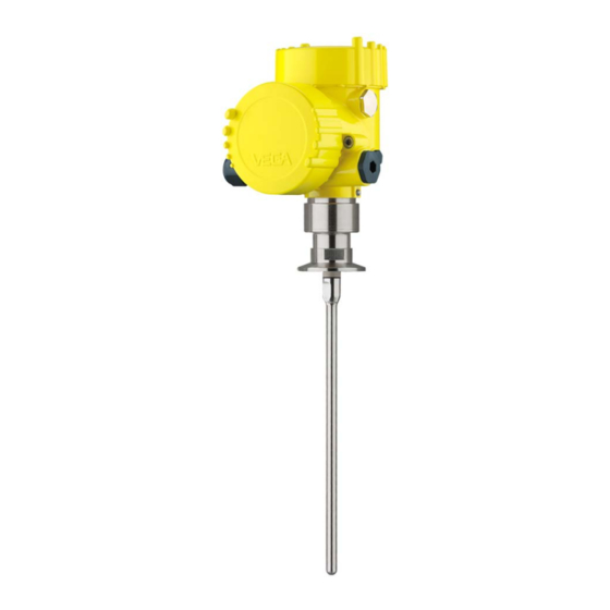
Tdr sensor for continuous level and interface measurement of liquids
Hide thumbs
Also See for VEGAFLEX 83:
- Operating instructions manual (100 pages) ,
- Operating instruction (92 pages) ,
- Quick setup manual (20 pages)

Related Manuals for Vega VEGAFLEX 83


Summary of Contents for Vega VEGAFLEX 83
- Page 1 Operating Instructions TDR sensor for continuous level and interface measurement of liquids VEGAFLEX 83 Modbus and Levelmaster protocol Converter version in second chamber Polished rod probe Document ID: 41843...
-
Page 2: Table Of Contents
Set up with the quick setup ..................... 49 Saving the parameterisation data ................... 51 Diagnostics and servicing ....................52 Maintenance ........................52 Diagnosis memory ......................52 Status messages ......................53 Rectify faults ........................56 VEGAFLEX 83 • Modbus and Levelmaster protocol... - Page 3 10.8 Industrial property rights ....................85 10.9 Trademark ........................85 Safety instructions for Ex areas Take note of the Ex specific safety instructions for Ex applications. These instructions are attached as documents to each instrument with Ex approval and are part of the operating instructions. Editing status: 2021-08-19 VEGAFLEX 83 • Modbus and Levelmaster protocol...
-
Page 4: About This Document
Symbols used Document ID This symbol on the front page of this instruction refers to the Docu- ment ID. By entering the Document ID on www.vega.com you will reach the document download. Information, note, tip: This symbol indicates helpful additional infor- mation and tips for successful work. -
Page 5: For Your Safety
During work on and with the device, the required personal protective equipment must always be worn. Appropriate use VEGAFLEX 83 is a sensor for continuous level measurement. You can find detailed information about the area of application in chapter "Product description". Operational reliability is ensured only if the instrument is properly used according to the specifications in the operating instructions manual as well as possible supplementary instructions. -
Page 6: Namur Recommendations
That is why we have introduced an environment management system with the goal of continuously improving company environmental pro- tection. The environment management system is certified according to DIN EN ISO 14001. Please help us fulfil this obligation by observing the environmental instructions in this manual: • Chapter "Packaging, transport and storage" • Chapter "Disposal" VEGAFLEX 83 • Modbus and Levelmaster protocol... -
Page 7: Product Description
Scope of this operating This operating instructions manual applies to the following instrument instructions versions: • Hardware from 1.0.0 • Software from 1.3.0 • Only for instrument versions without SIL qualification Type label The type label contains the most important data for identification and use of the instrument: VEGAFLEX 83 • Modbus and Levelmaster protocol... - Page 8 Alternatively, you can access the data via your smartphone: • Download the VEGA Tools app from the "Apple App Store" or the "Google Play Store" • Scan the QR-code on the type label of the device or •...
-
Page 9: Principle Of Operation
Fig. 2: Position of Modbus and sensor electronics Modbus electronics Sensor electronics Principle of operation The VEGAFLEX 83 is a level sensor with polished rod probe for Application area continuous level or interface measurement, particularly suitable for applications in the food processing and pharmaceutical industry. - Page 10 The dielectric constant must be 10 higher than the dielectric constant of the upper medium, preferably electrically conductive. Example: upper medium dielectric constant 2, lower medium at least dielectric constant 12. Gas phase (L3) • Air or gas mixture VEGAFLEX 83 • Modbus and Levelmaster protocol...
-
Page 11: Packaging, Transport And Storage
The instructions for the listed accessories can be found in the down- load area on our homepage. PLICSCOM The display and adjustment module is used for measured value indi- cation, adjustment and diagnosis. The integrated Bluetooth module (optional) enables wireless adjust- ment via standard adjustment devices. VEGAFLEX 83 • Modbus and Levelmaster protocol... - Page 12 Rod segments: 450 … 480 mm (17.72 … 18.9 in) • End segment: 26 … 480 mm (1.02 … 18.9 in) Centering If you mount the VEGAFLEX 83 in a bypass tube or standpipe, you have to avoid contact to the bypass tube by using a spacer at the probe end. VEGAFLEX 83 • Modbus and Levelmaster protocol...
-
Page 13: Mounting
These are mainly: • Active measuring component • Process fitting • Process seal Process conditions in particular are: • Process pressure • Process temperature VEGAFLEX 83 • Modbus and Levelmaster protocol... -
Page 14: Mounting Instructions
Type of vessel Plastic vessel/Glass vessel The guided microwave principle requires a metallic surface on the process fitting. Therefore, in plastic vessels, etc., use an instru- ment version with flange (from DN 50) or place a metal sheet (ø > 200 mm/8 in) beneath the process fitting when screwing it in. Make sure that the plate has direct contact with the process fitting. When mounting rod or cable probes in vessels without metal walls, e.g. in plastic vessels, the measured value can be influenced by strong electromagnetic fields (emitted interference according to EN 61326: class A). In this case, use a probe with coaxial version. VEGAFLEX 83 • Modbus and Levelmaster protocol... - Page 15 In such cases, always carry out a false signal suppression after mounting. You can find further information under "Setup procedure". ≤ 150 mm ( 5.91") DN25 ... DN150 > DN150 ... DN200 ≤ 100 mm ( 3.94") Fig. 7: Mounting socket When welding the nozzle, make sure that the nozzle is flush with the vessel top. VEGAFLEX 83 • Modbus and Levelmaster protocol...
- Page 16 Keep in mind that a min. distance must be maintained below the reference plane and possibly also at the end of the probe - measure- ment in these areas is not possible (blocking distance). The length of the cable can be used all the way to the end only when measuring VEGAFLEX 83 • Modbus and Levelmaster protocol...
- Page 17 Screw the enclosed lid with slotted nut onto the instrument side of the process fitting and tighten the nut with a torque of 20 Nm. Make sure that no liquid or contamination penetrates into the housing or the process side. After autoclaving, screw the lid off again and place the housing verti- cally on the side of the process fitting. Tighten the slotted nut with a torque of 20 Nm. VEGAFLEX 83 • Modbus and Levelmaster protocol...
- Page 18 ø w DIN DN25, DN32, DN40 / 1", 1½" ø 50,5 DIN DN50 / 2" ø 64 DIN DN65 / 3" ø 91 Fig. 10: Autoclaved version Groove nut 2 Process fitting 3 Cover with groove nut VEGAFLEX 83 • Modbus and Levelmaster protocol...
-
Page 19: Connecting To Power Supply And Bus System
In the case of instrument housings with self-sealing NPT threads, it is not possible to have the cable entries screwed in at the factory. The free openings for the cable glands are therefore covered with red dust protection caps as transport protection. VEGAFLEX 83 • Modbus and Levelmaster protocol... -
Page 20: Connecting
1. Unscrew the housing lid 2. Loosen compression nut of the cable gland and remove blind plug 3. Remove approx. 10 cm (4 in) of the cable mantle (signal output), strip approx. 1 cm (0.4 in) insulation from the ends of the indi- vidual wires 4. Insert the cable into the sensor through the cable entry VEGAFLEX 83 • Modbus and Levelmaster protocol... - Page 21 The terminal blocks are pluggable and can be removed from the housing insert. To do this, lift the terminal block with a small screwdriv- er and pull it out. When inserting the terminal block again, you should hear it snap in. VEGAFLEX 83 • Modbus and Levelmaster protocol...
-
Page 22: Wiring Plan
Internal connection to the connection compartment For display and adjustment module or interface adapter Connection compartment MODBUS power supply off on Fig. 14: Connection compartment USB interface 2 Slide switch for integrated termination resistor (120 Ω) Modbus signal Voltage supply Terminal Function Polarity Voltage supply VEGAFLEX 83 • Modbus and Levelmaster protocol... -
Page 23: Double Chamber Housing With Vegadis-Adapter
Fig. 16: Top view of the M12 x 1 plug connector Pin 1 Pin 2 Pin 3 Pin 4 Contact pin Colour, connection ca- Terminal, electronics ble in the sensor module Pin 1 Brown Pin 2 White Pin 3 Blue Pin 4 Black VEGAFLEX 83 • Modbus and Levelmaster protocol... -
Page 24: Switch-On Phase
• Status byte goes to fault value Then the actual measured value is output to the signal cable. The value takes into account settings that have already been carried out, e.g. default setting. VEGAFLEX 83 • Modbus and Levelmaster protocol... -
Page 25: Set Up The Sensor With The Display And Adjustment Module
The display and adjustment module is powered by the sensor, an ad- ditional connection is not necessary. Fig. 17: Insertion of the display and adjustment module Note: If you intend to retrofit the instrument with a display and adjustment module for continuous measured value indication, a higher lid with an inspection glass is required. VEGAFLEX 83 • Modbus and Levelmaster protocol... -
Page 26: Adjustment System
[OK] will not be saved. Switch-on phase After switching on, the VEGAFLEX 83 carries out a short self-test where the device software is checked. The output signal transmits a fault signal during the switch-on phase. The following information is displayed on the display and adjustment module during the startup procedure: •... -
Page 27: Parameter Adjustment - Quick Setup
• Min. adjustment • False signal suppression You can find the description of the individual menu items in the follow- ing chapter "Parameter adjustment - Extended adjustment". Parameter adjustment - Extended adjustment For technically demanding measuring points, you can carry out extended settings in "Extended adjustment". Main menu The main menu is divided into five sections with the following func- tions: VEGAFLEX 83 • Modbus and Levelmaster protocol... - Page 28 You can enter names with max. 19 characters. The character set comprises: • Capital letters from A … Z • Numbers from 0 … 9 • Special characters + - / _ blanks Units In this menu item you select the distance unit and the temperature unit. VEGAFLEX 83 • Modbus and Levelmaster protocol...
- Page 29 Application - Medium, In this menu item, you can define the type of medium (product). dielectric constant This menu item is only available if you have selected level measure- ment under the menu item "Application". You can choose between the following medium types: VEGAFLEX 83 • Modbus and Levelmaster protocol...
- Page 30 In this menu item you can enter the max. adjustment for the level. With interface measurement this is the maximum total level. Adjust the requested percentage value with [+] and store with [OK]. VEGAFLEX 83 • Modbus and Levelmaster protocol...
- Page 31 As an alternative, you have the possibility taking over the adjustment of the level measurement also for the interface. Enter the respective distance value in m for the surface of the upper medium corresponding to the percentage value. VEGAFLEX 83 • Modbus and Levelmaster protocol...
- Page 32 In the following, you have to enter the values for your vessel, for example the vessel height and the socket correction. VEGAFLEX 83 • Modbus and Levelmaster protocol...
- Page 33 < 3.6 mA. Current output, min./max. In the menu item "Current output Min./Max.", you determine the reac- tion of the current output during operation. The default setting is min. current 3.8 mA and max. current 20.5 mA. VEGAFLEX 83 • Modbus and Levelmaster protocol...
- Page 34 The menu item "Delete" is used to completely delete an already cre- ated false signal suppression. This is useful if the saved false signal suppression no longer matches the metrological conditions in the vessel. VEGAFLEX 83 • Modbus and Levelmaster protocol...
- Page 35 This menu item enables the setting of the requested national lan- guage. In delivery status, the sensor is set to English. Displayed value 1 In this menu item, you define the indication of the measured value on the display. You can display two different measured values. In this menu item, you define measured value 1. The default setting for the displayed value 1 is "Filling height Level". VEGAFLEX 83 • Modbus and Levelmaster protocol...
- Page 36 If you have selected interface measurement under the menu item "Setup - Application", the peak values of the interface measurement are displayed in addition to the peak values of the level measurement. VEGAFLEX 83 • Modbus and Levelmaster protocol...
- Page 37 This menu item displays the peak values of the electronics tempera- ture as well as the dielectric constant. In another window you can carry out a reset of the two peak values separately. VEGAFLEX 83 • Modbus and Levelmaster protocol...
- Page 38 With the menu item "Setup" the echo curve it is possible to save at the time of setup. This is generally recommended; for using the Asset Management functions it is necessary. If possible, the curve should be saved with a low level in the vessel. VEGAFLEX 83 • Modbus and Levelmaster protocol...
- Page 39 After this menu window, the reset process is carried out. No further safety inquiry follows. The following reset functions are available: Delivery status: Restores the parameter settings at the time of ship- ment from the factory, incl. order-specific settings. Any stored false VEGAFLEX 83 • Modbus and Levelmaster protocol...
- Page 40 0 mm Linearisation - Vessel height Probe length Scaling variable - Level Volume in l Scaling unit - Level Litres Scaling format - Level Without decimal positions Scaling level - 100 % corresponds to VEGAFLEX 83 • Modbus and Levelmaster protocol...
- Page 41 The following data or settings for adjustment of the display and ad- justment module are saved: • All data of the menu "Setup" and "Display" • In the menu "Additional adjustments" the items "Reset, Date/Time" • Special parameters VEGAFLEX 83 • Modbus and Levelmaster protocol...
- Page 42 Scaling level - Scaling format In menu item "Scaling format" you define the scaling format on the display and the scaling of the measured level value for 0 % and 100 %. VEGAFLEX 83 • Modbus and Levelmaster protocol...
- Page 43 In menu item "Current output, variable" you specify which measured output size variable the current output refers to. In menu item "Current output, adjustment" you can assign a respec- Current output - Current output adjustment tive measured value to the current output. VEGAFLEX 83 • Modbus and Levelmaster protocol...
- Page 44 6.5.5 Info Device name In this menu, you read out the instrument name and the instrument serial number. Instrument version In this menu item, the hardware and software version of the sensor is displayed. VEGAFLEX 83 • Modbus and Levelmaster protocol...
-
Page 45: Saving The Parameterisation Data
In the display and adjust- If the instrument is equipped with a display and adjustment module, ment module the parameter adjustment data can be saved therein. The procedure is described in menu item "Copy device settings". VEGAFLEX 83 • Modbus and Levelmaster protocol... -
Page 46: Setting Up Sensor And Modbus Interface With Pactware
Scope of the parameter adjustment: • Sensor electronics • Modbus electronics Fig. 21: Connecting the PC via USB to the Modbus electronics 1 USB cable to the PC To the RS 485 cable Connection of the PC to the RS 485 cable is carried out via a stand- ard interface adapter RS 485/USB. VEGAFLEX 83 • Modbus and Levelmaster protocol... -
Page 47: Parameter Adjustment With Pactware
Further setup steps are described in the operating instructions manu- al "DTM Collection/PACTware" attached to each DTM Collection and which can also be downloaded from the Internet. Detailed descrip- tions are available in the online help of PACTware and the DTMs. VEGAFLEX 83 • Modbus and Levelmaster protocol... -
Page 48: Set Instrument Address
"Software". The full version is avail- able on CD from the agency serving you. Set instrument address The VEGAFLEX 83 requires an address for participating as a sensor in the Modbus communication. The addess setting is carried out via a PC with PACTware/DTM or Modbus RTU. -
Page 49: Set Up With The Quick Setup
The quick setup is another option for parameter adjustment of the sensor. It allows fast, convenient adjustment of the most important parameters to adapt the sensor quickly to standard applications. To use it, select the function "Quick setup" in the start screen. VEGAFLEX 83 • Modbus and Levelmaster protocol... - Page 50 2 Extended adjustment Maintenance Quick setup With quick setup you can carry out the parameter adjustment of VEGAFLEX 83 for your application in just a few simple steps. The assistant-driven adjustment includes the basic settings for simple, reliable setup and commissioning. Information: If the function is inactive, then possibly no instrument is connected.
-
Page 51: Saving The Parameterisation Data
7 Setting up sensor and Modbus interface with PACTware Saving the parameterisation data We recommend documenting or saving the parameterisation data via PACTware. That way the data are available for multiple use or service purposes. VEGAFLEX 83 • Modbus and Levelmaster protocol... -
Page 52: Diagnostics And Servicing
Up to 500 events are automatically stored with a time stamp in the sensor (non-deletable). Each entry contains date/time, event type, event description and value. Event types are for example: • Modification of a parameter • Switch-on and switch-off times • Status messages (according to NE 107) • Error messages (according to NE 107) The data are read out via a PC with PACTware/DTM or the control system with EDD. VEGAFLEX 83 • Modbus and Levelmaster protocol... -
Page 53: Status Messages
Failure: Due to a malfunction in the instrument, a fault signal is output. This status message is always active. It cannot be deactivated by the user. Function check: The instrument is being worked on, the measured value is temporarily invalid (for example during simulation). This status message is inactive by default. VEGAFLEX 83 • Modbus and Levelmaster protocol... - Page 54 Communication Send instrument for repair error F125 Temperature of the electronics in the Check ambient temperature Bit 7 non-specified range Impermissible Insulate electronics electronics tem- Use instrument with higher temper- perature ature range VEGAFLEX 83 • Modbus and Levelmaster protocol...
- Page 55 Level echo in the close range not Reduce level Bit 9 of available Byte 14 … 24 Overfilling 100 % adjustment: Increase value Check mounting socket Remove possible interfering signals in the close range Use coaxial probe VEGAFLEX 83 • Modbus and Levelmaster protocol...
-
Page 56: Rectify Faults
The operator of the system is responsible for taking suitable meas- tion occurs ures to rectify faults. The first measures are: Fault rectification • Evaluation of fault messages • Checking the output signal • Treatment of measurement errors VEGAFLEX 83 • Modbus and Levelmaster protocol... - Page 57 If the output level is constant, the cause could also be the fault setting of the output to "Hold value". If the level is too low, the reason could be a line resistance that is too high VEGAFLEX 83 • Modbus and Levelmaster protocol...
- Page 58 Level echo is no longer detected in the Eliminate false signals in the close range ≥ 100 % or 0 m distance close range due to false signals in the Check installation conditions close range. The sensor goes into over- If possible, switch off the function "Over- fill protection mode. The max. level (0 m fill protection" distance) as well as the status message "Overfill protection" are output. time VEGAFLEX 83 • Modbus and Levelmaster protocol...
-
Page 59: Exchanging The Electronics Module
24 hour service hotline Should these measures not be successful, please call in urgent cases the VEGA service hotline under the phone no. +49 1805 858550. The hotline is also available outside normal working hours, seven days a week around the clock. -
Page 60: Exchanging The Rod
6. Enter new probe length and if necessary the new probe type and then carry out a fresh adjustment (see "Setup procedure, Carry- ing out min. adjustment - Carrying out max. adjustment"). Exchanging the seal Exchanging the seal If necessary, the seal of the probe can be exchanged. VEGAFLEX 83 • Modbus and Levelmaster protocol... - Page 61 2. Screw out the loosened measuring rod by hand 3. Push the enclosed new rod seal ring (9.25 x 1.78) onto the thread of the measuring rod. Fig. 28: Remove measuring rod Sealing ring (9.25 x 1.78) 4. Loosen process fitting with a suitable wrench. 5. Unscrew the process fitting manually from the sensor. 6. Remove the old process seal out of the process fitting. 7. Insert the attached new process seal ring (15.54 x 2.62) into the process fitting. VEGAFLEX 83 • Modbus and Levelmaster protocol...
-
Page 62: Software Update
11. Exert counterforce manually and tighten the rod on the flat sur- faces with a torque of max. 4.5 Nm (3.32 lbf ft). Information: Please maintain the specified torque so that the max. tensile strength of the connection remains. Software update The following components are required to update the instrument software: • Instrument • Voltage supply • Interface adapter VEGACONNECT • PC with PACTware VEGAFLEX 83 • Modbus and Levelmaster protocol... -
Page 63: How To Proceed If A Repair Is Necessary
• Attach the completed form and, if need be, also a safety data sheet outside on the packaging • Ask the agency serving you to get the address for the return ship- ment. You can find the agency on our homepage. VEGAFLEX 83 • Modbus and Levelmaster protocol... -
Page 64: Dismount
Pass the instrument directly on to a specialised recycling company and do not use the municipal collecting points. If you have no way to dispose of the old instrument properly, please contact us concerning return and disposal. VEGAFLEX 83 • Modbus and Levelmaster protocol... -
Page 65: Supplement
Ʋ Instrument weight (depending on approx. 0.8 … 8 kg (0.176 … 17.64 lbs) process fitting) Ʋ Rod: ø 8 mm (0.315 in), polished approx. 400 g/m (4.3 oz/ft) Probe length L (from seal surface) Ʋ Rod: ø 8 mm (0.315 in), polished up to 4 m (13.12 ft) - also possible for segmented rods Ʋ Trimming accuracy (rod) ±1 mm + 0.05 % of the rod length All wetted parts. Aluminium, stainless steel precision casting and Ex d housing VEGAFLEX 83 • Modbus and Levelmaster protocol... - Page 66 Ʋ Vessel metallic, ø 1 m (3.281 ft), centric mounting, process fit- ting flush with the vessel ceiling Ʋ Medium Water/Oil (dielectric constant ~2.0) Ʋ Mounting Probe end does not touch the vessel bottom Sensor parameter adjustment No gating out of false signals carried out With interface measurement = 2.0 VEGAFLEX 83 • Modbus and Levelmaster protocol...
- Page 67 Lower blocking distance (see following diagrams - grey section) Typical deviation - Interface measure- ± 5 mm (0.197 in) ment Typical deviation - Total level interface See following diagrams measurement Typical deviation - Level measurement See following diagrams 4)5) Depending on the mounting conditions, deviations can occur which can be rectified by adapting the adjustment or changing the measured value offset in the DTM service mode. The blocking distances can be optimized via a false signal suppression. VEGAFLEX 83 • Modbus and Levelmaster protocol...
- Page 68 ") Fig. 32: Deviation VEGAFLEX 83 in rod version in oil Blocking distance (no measurement possible in this area) Probe length Non-repeatability ≤ ±1 mm Variables influencing measurement accuracy Temperature drift - Digital output ±3 mm/10 K relating to the max. measuring range or max. 10 mm (0.394 in) Additional deviation through electromag- < ±10 mm (< ±0.394 in) netic interference acc. to EN 61326 VEGAFLEX 83 • Modbus and Levelmaster protocol...
- Page 69 Vessel pressure relating to the flange see supplementary instructions manual "Flanges ac- nominal pressure stage cording to DIN-EN-ASME-JIS" Time span after a sudden measuring distance change by max. 0.5 m in liquid applications, max 2 m with bulk solids applications, until the output signal has taken for the first time 90 % of the final value (IEC 61298-2). VEGAFLEX 83 • Modbus and Levelmaster protocol...
- Page 70 Electromechanical data - version IP67 Options of the cable entry Ʋ Cable entry M20 x 1.5; ½ NPT Ʋ Cable gland M20 x 1.5; ½ NPT (cable ø see below table) Ʋ Blind plug M20 x 1.5; ½ NPT Ʋ Closing cap ½ NPT VEGAFLEX 83 • Modbus and Levelmaster protocol...
- Page 71 Protection, depending on housing version Ʋ Plastic housing IP67 acc. to IEC 60529, Type 4X acc. to NEMA Ʋ Aluminium housing; stainless steel IP68 (0.2 bar) acc. to IEC 60529, Type 6P acc. to NEMA housing - precision casting Galvanic separation between electronics and metal housing parts VEGAFLEX 83 • Modbus and Levelmaster protocol...
-
Page 72: Device Communication Modbus
General configuration of the host The data exchange with status and variables between field device and host is carried out via register. For this, a configuration in the host is required. Floating point numbers with short prevision (4 bytes) according to IEEE 754 are transmitted with individually selectable order of the data bytes (byte transmission order). This "Byte transmission order" is determined in the parameter "Format Code". Hence the RTU knows the registers of the VEGAFLEX 83 which must be contacted for the variables and status information. Format Code Byte transmission order ABCD... - Page 73 Quarternary Variable in Byte Order of Register 3000 Status 1400 DWord See Register 100 1402 Primary Variable in Byte Order CDAB Status 1412 DWord See Register 100 1414 Secondary Variable in Byte Order CDAB Status 1424 DWord See Register 100 VEGAFLEX 83 • Modbus and Levelmaster protocol...
- Page 74 Unit Codes for Register 104, 108, 112, 116 Unit Code Measurement Unit Degree Celsius Degree Fahrenheit US Gallon Liters Imperial Gallons Cubic Meters Feet Meters Barrels Inches Centimeters Millimeters Cubic Yards Cubic Feet VEGAFLEX 83 • Modbus and Levelmaster protocol...
-
Page 75: Modbus Rtu Commands
Function Code 1 Byte 0x06 Start Address 2 Bytes 0x0000 to 0xFFFF Number of Registers 2 Bytes Data Response: Function Code 1 Byte 0x04 Start Address 2 Bytes Register Value 2 Bytes Data VEGAFLEX 83 • Modbus and Levelmaster protocol... - Page 76 With this function code, the sensor ID on Modbus is queried. Parameter Length Code/Data Request: Function Code 1 Byte 0x11 Response: Function Code 1 Byte 0x11 Byte Number 1 Byte Sensor ID 1 Byte Run Indicator Status 1 Byte VEGAFLEX 83 • Modbus and Levelmaster protocol...
-
Page 77: Levelmaster Commands
List of Object value 1 Byte Depending on the Object ID 10.5 Levelmaster commands The VEGAFLEX 83 is also suitable for connection to the following RTUs with Levelmaster protocol. The Levelmaster protocol is often called "Siemens" "Tank protocol". Protocol ABB Totalflow... - Page 78 U**N? Response: Report Level (and Temperature) 6 characters ASCII UuuNnn Assign Unit Number Parameter Length Code/Data Request: Assign Unit Number 6 characters ASCII UuuNnn Response: Assign Unit Number 6 characters ASCII UuuNOK uu = new Address VEGAFLEX 83 • Modbus and Levelmaster protocol...
- Page 79 Report Receive to Transmit Delay Parameter Length Code/Data Request: Report Receive to Transmit 4 characters ASCII UuuR Delay Response: Report Receive to Transmit 7 characters ASCII UuuRmmm Delay mmm = milliseconds (50 up to 250), default = 127 ms VEGAFLEX 83 • Modbus and Levelmaster protocol...
-
Page 80: Configuration Of Typical Modbus Hosts
Thermo Electron Autopilot - Register address for 1300 is address 1300 • Bristol ControlWave Micro - Register address for 1302 is address 1303 • ScadaPack - Register address for 1302 is address 31303 VEGAFLEX 83 • Modbus and Levelmaster protocol... -
Page 81: Dimensions
10 Supplement 10.7 Dimensions The following dimensional drawings represent only an extract of all possible versions. Detailed dimensional drawings can be downloaded at www.vega.com/downloads under "Drawings". Housing ~ 87 mm ~ 84 mm (3.43") ø 84 mm (3.31") ø 79 mm (3.31") - Page 82 10 Supplement VEGAFLEX 83, rod version ø 8 mm (0.315 in), polished ø 8 mm (0.32") Fig. 36: VEGAFLEX 83, rod version ø 8 mm (0.315 in), polished Sensor length, see chapter "Technical data" VEGAFLEX 83 • Modbus and Levelmaster protocol...
- Page 83 10 Supplement VEGAFLEX 83, rod version ø 8 mm (0.315 in), polished - autoclaved version ø 54 mm (2.13") ø w ø w DIN DN25, DN32, DN40 / 1", 1½" ø 50,5 DIN DN50 / 2" ø 64 DIN DN65 / 3"...
- Page 84 Extension components - rod extension ø 8 mm (0.315 in), polished ø13 mm (0.51") SW 10 ø8 mm (0.31") Fig. 38: Extension rods with ø 8 mm (0.315 in) 1 Version with threaded fitting 2 Version with flange connection A Basic extension rod with ø 8 mm (0.315 in) B Extension rod with ø 8 mm (0.315 in) C End rod with ø 8 mm (0.315 in) Length (order length) VEGAFLEX 83 • Modbus and Levelmaster protocol...
-
Page 85: Industrial Property Rights
Les lignes de produits VEGA sont globalement protégées par des droits de propriété intellec- tuelle. Pour plus d'informations, on pourra se référer au site www.vega.com. VEGA lineas de productos están protegidas por los derechos en el campo de la propiedad indus- trial. Para mayor información revise la pagina web www.vega.com. - Page 86 Replacement parts – Display and adjustment module with heating 12 Factory calibration date 45 – Rod components 12 False signal suppression 34 – Spacer 12 Fault Reset 39 – Rectification 56 Fault rectification 56 Functional principle 9 VEGAFLEX 83 • Modbus and Levelmaster protocol...
- Page 87 INDEX Scaling measured value 42, 43 Sensor characteristics 45 Service hotline 59 Simulation 38 Special parameters 44 Type label 7 Type of medium 29 Units 28 VEGAFLEX 83 • Modbus and Levelmaster protocol...
- Page 88 Subject to change without prior notice © VEGA Grieshaber KG, Schiltach/Germany 2021 VEGA Grieshaber KG Am Hohenstein 113 Phone +49 7836 50-0 77761 Schiltach E-mail: info.de@vega.com...
Need help?
Do you have a question about the VEGAFLEX 83 and is the answer not in the manual?
Questions and answers