Vega VEGAFLEX 83 Operating Instructions Manual
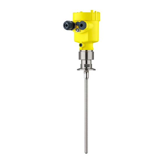
Tdr sensor for continuous level and interface measurement of liquids
Hide thumbs
Also See for VEGAFLEX 83:
- Operating instructions manual (100 pages) ,
- Operating instruction (92 pages) ,
- Quick setup manual (20 pages)

Related Manuals for Vega VEGAFLEX 83


Summary of Contents for Vega VEGAFLEX 83
- Page 1 Operating Instructions TDR sensor for continuous level and interface measurement of liquids VEGAFLEX 83 Two-wire: 4 … 20 mA/HART Polished rod probe With SIL qualification Document ID: 44225...
-
Page 2: Table Of Contents
Set up with smartphone/tablet/PC/notebook via Bluetooth ..........55 Preparations ........................55 Connecting ........................56 Sensor parameter adjustment ..................57 Setup with PACTware ......................58 Connect the PC ......................58 Parameter adjustment ....................58 VEGAFLEX 83 • Two-wire: 4 … 20 mA/HART... - Page 3 13.5 Environment management system ................. 75 14 Supplement ..........................77 14.1 Technical data ........................ 77 14.2 Dimensions ........................86 14.3 Industrial property rights ....................91 14.4 Trademark ........................91 Editing status: 2024-08-28 VEGAFLEX 83 • Two-wire: 4 … 20 mA/HART...
-
Page 4: About This Document
Symbols used Document ID This symbol on the front page of this instruction refers to the Docu- ment ID. By entering the Document ID on www.vega.com you will reach the document download. Information, note, tip: This symbol indicates helpful additional infor- mation and tips for successful work. -
Page 5: For Your Safety
During work on and with the device, the required personal protective equipment must always be worn. Appropriate use VEGAFLEX 83 is a sensor for continuous level measurement. You can find detailed information about the area of application in chapter "Product description". Operational reliability is ensured only if the instrument is properly used according to the specifications in this document as well as pos- sible supplementary instructions. - Page 6 Installations in Canada shall comply with the relevant requirements of the Canadian Electrical Code (CEC Part I) (Canada). A Class 2 power supply unit has to be used for the installation in the USA and Canada. VEGAFLEX 83 • Two-wire: 4 … 20 mA/HART...
-
Page 7: Product Description
Optionally an autoclaved version with separable housing is available. Due to the qualification up to SIL2 or homogeneous redundant up to SIL3 (IEC 61508) the VEGAFLEX 83 is suitable for the use in safety- instrumented systems (SIS). The safety function (SIF) can be a monitoring of the max. or min. level or a combination of both. - Page 8 High frequency microwave impulses are guided along a steel cable or terface measurement rod. Upon reaching the medium surface, a part of the microwave im- pulses is reflected. The other part passes through the upper product and is reflected by the interface. The running times to the two product layers are processed by the instrument. VEGAFLEX 83 • Two-wire: 4 … 20 mA/HART...
- Page 9 Example: upper medium dielectric constant 2, lower medium at least dielectric constant 12. Gas phase (L3) • Air or gas mixture • Gas phase - dependent on the application, gas phase does not always exist (d2 = 0) VEGAFLEX 83 • Two-wire: 4 … 20 mA/HART...
-
Page 10: Packaging, Transport And Storage
The integrated Bluetooth module (optional) enables wireless adjust- ment via standard adjustment devices. VEGACONNECT The interface adapter VEGACONNECT enables the connection of communication-capable instruments to the USB interface of a PC. VEGAFLEX 83 • Two-wire: 4 … 20 mA/HART... -
Page 11: External Housing
End segment: 26 … 480 mm (1.02 … 18.9 in) Centering If you mount the VEGAFLEX 83 in a bypass tube or standpipe, you have to avoid contact to the bypass tube by using a spacer at the probe end. -
Page 12: Mounting
These are mainly: • Active measuring component • Process fitting • Process seal Process conditions in particular are: • Process pressure • Process temperature VEGAFLEX 83 • Two-wire: 4 … 20 mA/HART... -
Page 13: Mounting Instructions
The guided microwave principle requires a metallic surface on the process fitting. Therefore, in plastic vessels, etc., use an instru- ment version with flange (from DN 50) or place a metal sheet (ø > 200 mm/8 in) beneath the process fitting when screwing it in. Make sure that the plate has direct contact with the process fitting. When mounting rod or cable probes in vessels without metal walls, e.g. in plastic vessels, the measured value can be influenced by strong electromagnetic fields (emitted interference according to EN 61326: class A). In this case, use a probe with coaxial version. VEGAFLEX 83 • Two-wire: 4 … 20 mA/HART... - Page 14 In such cases, always carry out a false signal suppression after mounting. You can find further information under "Setup procedure". DN25 ... DN150 ≤ 150 mm ( 5.91") ≤ 100 mm ( 3.94") > DN150 ... DN200 Fig. 5: Mounting socket When welding the nozzle, make sure that the nozzle is flush with the vessel top. VEGAFLEX 83 • Two-wire: 4 … 20 mA/HART...
- Page 15 - measure- ment in these areas is not possible (blocking distance). The length of the cable can be used all the way to the end only when measuring VEGAFLEX 83 • Two-wire: 4 … 20 mA/HART...
- Page 16 You can find further information in the supplementary instructions of the rod and cable components. Autoclaved version For use in an autoclave, e.g. for sterilization, the VEGAFLEX 83 is available as autoclaved version. Hence you can separate the housing from the process fitting. Under very harsh ambient conditions, the autoclavable version can be optionally also combined with an external housing.
- Page 17 DIN DN25, DN32, DN40 / 1", 1½" ø 50,5 DIN DN50 / 2" ø 64 DIN DN65 / 3" ø 91 Fig. 8: Autoclaved version Groove nut 2 Process fitting Cover with groove nut VEGAFLEX 83 • Two-wire: 4 … 20 mA/HART...
-
Page 18: Connecting To Power Supply
In the case of instrument housings with self-sealing NPT threads, it is not possible to have the cable entries screwed in at the factory. The free openings for the cable glands are therefore covered with red dust protection caps as transport protection. VEGAFLEX 83 • Two-wire: 4 … 20 mA/HART... -
Page 19: Cable Screening And Grounding
4. Remove approx. 10 cm (4 in) of the cable mantle, strip approx. 1 cm (0.4 in) of insulation from the ends of the individual wires 5. Insert the cable into the sensor through the cable entry VEGAFLEX 83 • Two-wire: 4 … 20 mA/HART... -
Page 20: Wiring Plan - Single Chamber Housing
10. Reinsert the display and adjustment module, if one was installed 11. Screw the housing lid back on The electrical connection is finished. Wiring plan - single chamber housing The following illustration applies to the non-Ex, Ex ia and Ex d version. VEGAFLEX 83 • Two-wire: 4 … 20 mA/HART... -
Page 21: Wiring Plan - Double Chamber Housing
The following illustration applies to the non-Ex, Ex ia and Ex d version. Electronics compartment 4...20mA 6 7 8 Fig. 11: Electronics compartment - double chamber housing Internal connection to the connection compartment For display and adjustment module or interface adapter VEGAFLEX 83 • Two-wire: 4 … 20 mA/HART... -
Page 22: Connection Compartment
Fig. 13: Electronics compartment - double chamber housing Internal connection to the connection compartment For display and adjustment module or interface adapter Internal connection to the plug connector for external display and adjust- ment unit (optional) VEGAFLEX 83 • Two-wire: 4 … 20 mA/HART... -
Page 23: Double Chamber Housing With Vegadis-Adapter
Internal plug connection M12 x 1 plug connector Assignment of the plug connector Fig. 16: Top view of the M12 x 1 plug connector Pin 1 Pin 2 Pin 3 Pin 4 VEGAFLEX 83 • Two-wire: 4 … 20 mA/HART... -
Page 24: Wiring Plan - Version Ip66/Ip68 (1 Bar)
Fig. 18: Connection compartment, double chamber housing, supplementary electronics - additional current output 1 Current output (I) - Voltage supply of the sensor and signal output (with HART) 2 Additional current output (II) - Voltage supply and signal output (without HART) Ground terminal for connection of the cable screening Switch-on phase After connection of the device to power supply, the device first carries out a self-test: VEGAFLEX 83 • Two-wire: 4 … 20 mA/HART... - Page 25 PC • The output signal jumps briefly to the set fault current Then the actual measured value is output to the signal cable. The value takes into account settings that have already been carried out, e.g. default setting. VEGAFLEX 83 • Two-wire: 4 … 20 mA/HART...
-
Page 26: Functional Safety (Sil)
SIL rating and can be also found on our homepage via the search. Application area The instrument can be used for point level detection or level measure- ment of liquids and bulk solids in safety-instrumented systems (SIS) VEGAFLEX 83 • Two-wire: 4 … 20 mA/HART... -
Page 27: Safety Concept Of The Parameterization
The DTM suitable for the device in conjunction with an adjustment software according to the FDT/DTM standard, e. g. PACTware Note: For operation of the VEGAFLEX 83 an actual DTM Collection is re- quired. The modification of safety-relevant parameters is only possible with active connection to the instrument (online mode). -
Page 28: Setup Process
Each parameter change requires the release of the instrument through a PIN (see chapter "Setup steps - Lock adjustment"). In delivery status, the PIN is 0000. Change parameters Set up the VEGAFLEX 83 according to the specification in this oper- ating instructions and the Safety Manual. VEGAFLEX 83 • Two-wire: 4 … 20 mA/HART... - Page 29 If you have to interrupt the function, you can leave the VEGAFLEX 83 in the respective situation. As long as VEGAFLEX 83 is powered, the display and adjustment module remains in the currently set adjustment menu.
- Page 30 Then you carry out a comparison of two character strings. You must confirm that the character strings are identical. This is used to check the character presentation. Then you confirm that the serial number of your instrument has been carried over correctly. This is used to check device communication. Then, all modified parameters that have to be confirmed are listed. After this process is terminated, the safety function is again ensured. VEGAFLEX 83 • Two-wire: 4 … 20 mA/HART...
-
Page 31: Set Up With The Display And Adjustment Module
The display and adjustment module is powered by the sensor, an ad- ditional connection is not necessary. Fig. 19: Installing the display and adjustment module in the electronics compart- ment of the single chamber housing VEGAFLEX 83 • Two-wire: 4 … 20 mA/HART... -
Page 32: Adjustment System
– Confirm selected menu – Edit parameter – Save value • [->] key: – Change measured value presentation – Select list entry – Select editing position • [+] key: – Change value of the parameter VEGAFLEX 83 • Two-wire: 4 … 20 mA/HART... -
Page 33: Time Functions
[OK] will not be saved. Switch-on phase After switching on, the VEGAFLEX 83 carries out a short self-test where the device software is checked. The output signal transmits a fault signal during the switch-on phase. The following information is displayed on the display and adjustment module during the startup procedure: •... -
Page 34: Parameter Adjustment - Extended Adjustment
"Setup" should be selected one after the other and provided with the correct parameters. If possible, go through the items in the given sequence. The procedure is described below. The following submenu points are available: VEGAFLEX 83 • Two-wire: 4 … 20 mA/HART... - Page 35 In this menu item, you can select the application. You can choose between level measurement and interface measurement. You can also choose between measurement in a vessel or in a bypass or standpipe. VEGAFLEX 83 • Two-wire: 4 … 20 mA/HART...
- Page 36 This menu item is only available if you have selected interface meas- constant urement under the menu item "Application". In this menu item you can enter the dielectric constant of the upper medium. VEGAFLEX 83 • Two-wire: 4 … 20 mA/HART...
- Page 37 Adjust the requested percentage value with [+] and store with [OK]. Enter the suitable distance value in m for the empty vessel (e.g. distance from the flange to the probe end) corresponding to the per- centage value. The distance refers tot he sensor reference plane (seal surface of the process fitting). VEGAFLEX 83 • Two-wire: 4 … 20 mA/HART...
- Page 38 If you have selected interface measurement under the menu item "Application", you can adjust the damping for the level and the inter- face separately. The default setting is a damping of 0 s. VEGAFLEX 83 • Two-wire: 4 … 20 mA/HART...
- Page 39 Fig. 23: Vessel height and socket correction value D Vessel height +h Positive socket correction value -h Negative socket correction value VEGAFLEX 83 • Two-wire: 4 … 20 mA/HART...
- Page 40 Proceed as follows: Select first if the probe is covered or uncovered. If the probe is covered, enter the actual distance from the sensor to the product surface. All interfering signals in this section are detected by the sensor and stored. VEGAFLEX 83 • Two-wire: 4 … 20 mA/HART...
- Page 41 Confirm if the two character strings are identical. The verification texts are provided in German and in the case of all other menu languages, in English. Afterwards you confirm that the serial number of your instrument was carried over correctly. This is used to check device communication. VEGAFLEX 83 • Two-wire: 4 … 20 mA/HART...
- Page 42 This deviation depends on the the accuracy requirements of your measurement loop. Determine the permissible tolerance for the deviation. If you have to interrupt the function, you can leave the VEGAFLEX 83 in the respective situation. As long as VEGAFLEX 83 is powered, the display and adjustment module remains in the currently set adjustment menu.
- Page 43 If you have to interrupt the function test, you can leave the display and adjustment module of VEGAFLEX 83 in its current state. As long as VEGAFLEX 83 is powered, the display and adjustment module remains in the currently set adjustment menu.
- Page 44 In delivery status, the lighting is switched on. 7.3.3 Diagnostics Device status In this menu item, the device status is displayed. When the instrument displays a fault signal, you can here get detailed information on the failure reason. VEGAFLEX 83 • Two-wire: 4 … 20 mA/HART...
- Page 45 Peak indicator, additional sensor. The values are displayed in the menu item "Peak indicator Additional". This menu item displays the peak values of the electronics tempera- ture as well as the dielectric constant. VEGAFLEX 83 • Two-wire: 4 … 20 mA/HART...
- Page 46 Select the requested simulation variable and set the requested value. Caution: During simulation, the simulated value is output as 4 … 20 mA current value and digital HART signal. VEGAFLEX 83 • Two-wire: 4 … 20 mA/HART...
-
Page 47: Additional Adjustments
During the function test, the safety function must be treated as unsafe. Keep in mind that the function test influences downstream connected devices. You can find detailed information on the proof test in the Safety Manual (SIL). 7.3.4 Additional adjustments Date/Time In this menu item, the internal clock of the sensor is set. VEGAFLEX 83 • Two-wire: 4 … 20 mA/HART... - Page 48 Lock adjustment Locked Measurement loop name Sensor Units Distance unit: order-specific Temperature unit: order-specific Probe length Länge der Messsonde factory setting Type of medium Liquid Application Level, vessel Medium, dielectric constant Water-based, > 10 Superimposed gas phase VEGAFLEX 83 • Two-wire: 4 … 20 mA/HART...
- Page 49 Current output - Max. 20.5 mA Current output 2 - Output variable Distance - Level Second HART variable (SV) Current output 2 - Output characteristics 0 … 100 % correspond to 4 … 20 mA VEGAFLEX 83 • Two-wire: 4 … 20 mA/HART...
- Page 50 Device memory - Measured value memory - Stop recording Not active when memory is full Menu - Additional adjustments Menu item Default value 0000 Date Actual date Time Actual time Time - Format 24 hours VEGAFLEX 83 • Two-wire: 4 … 20 mA/HART...
- Page 51 We recommend to save the instrument adjustments. In case of an electronics exchange the saved parameter adjustment data relieve this process. Scaling level Since scaling is very extensive, scaling of the level value was divided into two menu items. VEGAFLEX 83 • Two-wire: 4 … 20 mA/HART...
- Page 52 Scaling interface - Scal- In menu item "Scaling format" you define the scaling format on the ing format display and the scaling of the measured interface value for 0 % and 100 %. VEGAFLEX 83 • Two-wire: 4 … 20 mA/HART...
-
Page 53: Current Output
In this menu item you gain access to the protected area where you can enter special parameters. In exceptional cases, individual parameters can be modified in order to adapt the sensor to special requirements. Change the settings of the special parameters only after having con- tacted our service staff. VEGAFLEX 83 • Two-wire: 4 … 20 mA/HART... -
Page 54: Save Parameter Adjustment Data
In the display and adjust- If the instrument is equipped with a display and adjustment module, ment module the parameter adjustment data can be saved therein. The procedure is described in menu item "Copy device settings". VEGAFLEX 83 • Two-wire: 4 … 20 mA/HART... -
Page 55: Set Up With Smartphone/Tablet/Pc/Notebook Via Bluetooth
PIN in the adjustment menu of the respective sensor, e.g. to "1111". Use "OK" to switch to the input menu. Basic adjustment Display Diagnostics Service Info Under the menu item "Service" you can change or deactivate the device PIN. VEGAFLEX 83 • Two-wire: 4 … 20 mA/HART... -
Page 56: Connecting
Bluetooth communication functions only if the actual sensor PIN dif- fers from the default setting "0000". Connecting Preparations Smartphone/Tablet Start the adjustment app and select the function "Setup". The smart- phone/tablet searches automatically for Bluetooth-capable instru- ments in the area. VEGAFLEX 83 • Two-wire: 4 … 20 mA/HART... -
Page 57: Sensor Parameter Adjustment
8 Set up with smartphone/tablet/PC/notebook via Bluetooth PC/Notebook Start PACTware and the VEGA project assistant. Select the device search via Bluetooth and start the search function. The device auto- matically searches for Bluetooth-capable devices in the vicinity. Connecting The message "Searching …" is displayed. -
Page 58: Setup With Pactware
Note: With power supply units with integrated HART resistance (internal resistance approx. 250 Ω), an additional external resistance is not necessary. This applies, e.g. to the VEGA instruments VEGAMET 381, VEGAMET 391. Common Ex separators are also usually equipped with a sufficient current limiting resistance. In such cases, the interface adapter can be connected parallel to the 4 … 20 mA cable (dashed line in the previous illustration). -
Page 59: Save Parameter Adjustment Data
Fig. 28: Example of a DTM view Save parameter adjustment data We recommend documenting or saving the parameterisation data via PACTware. That way the data are available for multiple use or service purposes. VEGAFLEX 83 • Two-wire: 4 … 20 mA/HART... -
Page 60: Set Up With Other Systems
This software is updated via the Internet and new EDDs are automatically accepted into the device catalogue of this software after they are released by the manufacturer. They can then be transferred to a Field Communicator. VEGAFLEX 83 • Two-wire: 4 … 20 mA/HART... -
Page 61: Diagnosis, Asset Management And Service
PACTware/DTM or the control system with EDD. Data are thus read out and also reset. Event memory Up to 500 events are automatically stored with a time stamp in the sensor (non-deletable). Each entry contains date/time, event type, event description and value. VEGAFLEX 83 • Two-wire: 4 … 20 mA/HART... -
Page 62: Asset Management Function
• Function check • Out of specification • Maintenance required and explained by pictographs: Fig. 29: Pictographs of the status messages Failure - red 2 Out of specification - yellow Function check - orange Maintenance required - blue VEGAFLEX 83 • Two-wire: 4 … 20 mA/HART... - Page 63 Check probe and exchange, if nec- Bit 13 of defective essary Byte 0 … 5 Probe loss F080 General software error Disconnect operating voltage briefly Bit 5 of Byte 0 … 5 General software error VEGAFLEX 83 • Two-wire: 4 … 20 mA/HART...
- Page 64 Status 0" 60 mins. C701 Parameter verification was inter- Finish parameter verification Bit 12 of rupted Byte 14 … 24 Parameter verifi- cation Tab. 8: Error codes and text messages, information on causes as well as corrective measures VEGAFLEX 83 • Two-wire: 4 … 20 mA/HART...
-
Page 65: Rectify Faults
Treatment of measurement errors A smartphone/tablet with the adjustment app or a PC/notebook with the software PACTware and the suitable DTM offer you further com- prehensive diagnostic possibilities. In many cases, the causes can be determined in this way and the faults eliminated. VEGAFLEX 83 • Two-wire: 4 … 20 mA/HART... - Page 66 Adapt min./max. adjustment too low or too high level Incorrect linearization curve Adapt linearization curve Running time error (small measurement Repeat setup error close to 100 %/serious error close to 0 %) time VEGAFLEX 83 • Two-wire: 4 … 20 mA/HART...
- Page 67 Remove contamination on the probe. Af- range during emptying ter having removed the source of the false signals, the false signal suppres- sion must be deleted. Carry out a new false signal suppression time VEGAFLEX 83 • Two-wire: 4 … 20 mA/HART...
-
Page 68: Exchanging The Electronics Module
24 hour service hotline Should these measures not be successful, please call in urgent cases the VEGA service hotline under the phone no. +49 1805 858550. The hotline is also available outside normal working hours, seven days a week around the clock. -
Page 69: Exchanging The Rod
3. Push the enclosed new seal ring onto the thread. 4. Screw the new rod carefully by hand onto the thread on the pro- cess fitting. 5. Exert counterforce manually and tighten the rod on the flat sur- faces with a torque of 4.5 Nm (3.32 lbf ft). VEGAFLEX 83 • Two-wire: 4 … 20 mA/HART... -
Page 70: Exchanging The Seal
FEPM (Vi 602 Extreme-ETP, COG), -10 … +150 °C Caution: Remember that the polished rod of the food version is very sensitive to damage and scratching. Use special tools in order to avoid damag- ing the surface. 1. Loosen the rod by applying a fork spanner to the flat surfaces (SW 10), provide counterforce manually on the process fitting VEGAFLEX 83 • Two-wire: 4 … 20 mA/HART... - Page 71 3. Push the enclosed new rod seal ring (9.25 x 1.78) onto the thread of the measuring rod. Fig. 32: Remove measuring rod 1 Sealing ring (9.25 x 1.78) 4. Loosen process fitting with a suitable wrench. 5. Unscrew the process fitting manually from the sensor. 6. Remove the old process seal out of the process fitting. 7. Insert the attached new process seal ring (15.54 x 2.62) into the process fitting. VEGAFLEX 83 • Two-wire: 4 … 20 mA/HART...
-
Page 72: Software Update
Information: Please maintain the specified torque so that the max. tensile strength of the connection remains. 11.8 Software update The following components are required to update the instrument software: • Instrument • Voltage supply • Interface adapter VEGACONNECT • PC with PACTware VEGAFLEX 83 • Two-wire: 4 … 20 mA/HART... -
Page 73: How To Proceed If A Repair Is Necessary
Print the generated instrument return form. Clean the instrument and pack it damage-proof. Send the printed instrument return form and possibly a safety data sheet together with the device. You will find the address for the return on the generated instrument return form. VEGAFLEX 83 • Two-wire: 4 … 20 mA/HART... -
Page 74: Dismount
If personal data is stored on the old device to be disposed of, delete it before disposal. If you have no way to dispose of the old instrument properly, please contact us concerning return and disposal. VEGAFLEX 83 • Two-wire: 4 … 20 mA/HART... -
Page 75: Certificates And Approvals
Protection of the environment is one of our most important duties. That is why we have introduced an environment management system with the goal of continuously improving company environmental pro- tection. The environment management system is certified according to DIN EN ISO 14001. VEGAFLEX 83 • Two-wire: 4 … 20 mA/HART... - Page 76 13 Certificates and approvals Help us to meet these requirements and observe the environmental instructions in the chapters "Packaging, transport and storage", "Dis- posal" of this instructions manual. VEGAFLEX 83 • Two-wire: 4 … 20 mA/HART...
-
Page 77: Supplement
PA, stainless steel, brass Ʋ Sealing, cable gland Ʋ Blind plug, cable gland Conductive connection Between ground terminal, process fitting and probe Process fittings Ʋ Clamp from 2" Ʋ Slotted nut from DN 32 PN 40 All wetted parts. VEGAFLEX 83 • Two-wire: 4 … 20 mA/HART... - Page 78 Ʋ First HART value (PV) Linearised percentage value, level Ʋ Second HART value (SV) Distance to the level Ʋ Third HART value (TV) Measurement reliability, level The output values can be assigned individually. VEGAFLEX 83 • Two-wire: 4 … 20 mA/HART...
- Page 79 Water/Oil (dielectric constant ~2.0) Ʋ Mounting Probe end does not touch the vessel bottom The indication values can be assigned individually. The indication values can be assigned individually. With interface measurement = 2.0. VEGAFLEX 83 • Two-wire: 4 … 20 mA/HART...
- Page 80 Typical deviation - Total level interface See following diagrams measurement Typical deviation - Level measurement See following diagrams 6)7) Depending on the mounting conditions, deviations can occur which can be rectified by adapting the adjustment or changing the measured value offset in the DTM service mode. The blocking distances can be optimized via a false signal suppression. VEGAFLEX 83 • Two-wire: 4 … 20 mA/HART...
- Page 81 -15 mm (-0.591 ") 0,08 m 0,2 m 0,04 m (3.15 (7.874 " " (1.575 ") Fig. 35: Deviation VEGAFLEX 83 in rod version in water Blocking distance (no measurement possible in this area) Probe length 15 mm (0.591 " 2 mm (0.079 ") -2 mm (-0.079 ") -10 mm (-0.394...
- Page 82 Products with high dielectric constant (> 10) up to 5 m/ minute Also for the additional current output (optional). Time span after a sudden measuring distance change by max. 0.5 m in liquid applications, max 2 m with bulk solids applications, until the output signal has taken for the first time 90 % of the final value (IEC 61298-2). VEGAFLEX 83 • Two-wire: 4 … 20 mA/HART...
- Page 83 Plastic housing Stainless steel housing (precision casting) Stainless steel housing (electropolished) SIP process temperature (SIP = Sterilization in place) Seals suitable for vapour: FFKM (Kalrez 6621) or EPDM (Freudenberg 70 EPDM 291) Vapour stratification up to 2 h +150 °C (+302 °F) Mechanical stress VEGAFLEX 83 • Two-wire: 4 … 20 mA/HART...
- Page 84 180 m (590.6 ft) Ʋ Min. bending radius (at 25 °C/77 °F) 25 mm (0.984 in) Ʋ Diameter approx. 8 mm (0.315 in) Ʋ Colour - Non-Ex version Black Ʋ Colour - Ex-version Blue VEGAFLEX 83 • Two-wire: 4 … 20 mA/HART...
- Page 85 Double chamber IP66/IP67 Type 4X Aluminium Single chamber IP66/IP68 (0.2 bar) Type 6P IP66/IP68 (1 bar) Type 6P Double chamber IP66/IP67 Type 4X IP66/IP68 (0.2 bar) Type 6P IP66/IP68 (1 bar) Type 6P VEGAFLEX 83 • Two-wire: 4 … 20 mA/HART...
-
Page 86: Dimensions
Protection rating (IEC 61010-1) 14.2 Dimensions The following dimensional drawings represent only an extract of all possible versions. Detailed dimensional drawings can be downloaded at www.vega.com/downloads under "Drawings". Plastic housing in protection rating IP66/IP67 ~ 69 mm ~ 84 mm (2.72") - Page 87 ~ 150 mm ~ 105 mm (5.91") (4.13") ø 86 mm ø 86 mm (3.39") (3.39") M16x1,5 M20x1,5 M20x1,5 M20x1,5/ ½ NPT Fig. 40: Housing versions with protection rating IP66/IP68 (1 bar), (with integrated display and adjustment module the housing is 18 mm/0.71 in higher) Aluminium - single chamber Aluminium - double chamber VEGAFLEX 83 • Two-wire: 4 … 20 mA/HART...
- Page 88 Stainless steel housing with protection rating IP66/IP68 (1 bar) ~ 105 mm ~ 150 mm (4.13") (5.91") ø 84 mm ø 84 mm (3.31") (3.31") M16x1,5 M20x1,5 M20x1,5 M20x1,5/ ½ NPT Fig. 42: Housing versions with protection rating IP66/IP68 (1 bar), (with integrated display and adjustment module the housing is 18 mm/0.71 in higher) Stainless steel single chamber (precision casting) Stainless steel double chamber (precision casting) VEGAFLEX 83 • Two-wire: 4 … 20 mA/HART...
- Page 89 VEGAFLEX 83, rod version ø 8 mm (0.315 in), polished ø 8 mm (0.32") Fig. 43: VEGAFLEX 83, rod version ø 8 mm (0.315 in), polished Sensor length, see chapter "Technical data" VEGAFLEX 83, rod version ø 8 mm (0.315 in), polished - autoclaved version ø 54 mm (2.13") ø w ø w DIN DN25, DN32, DN40 / 1", 1½"...
- Page 90 14 Supplement Extension components - rod extension ø 8 mm (0.315 in), polished ø13 mm (0.51") SW 10 ø8 mm (0.31") Fig. 45: Extension rods with ø 8 mm (0.315 in) 1 Version with threaded fitting A Basic extension rod with ø 8 mm (0.315 in) B Extension rod with ø 8 mm (0.315 in) C End rod with ø 8 mm (0.315 in) L Length (order length) VEGAFLEX 83 • Two-wire: 4 … 20 mA/HART...
-
Page 91: Industrial Property Rights
Les lignes de produits VEGA sont globalement protégées par des droits de propriété intellec- tuelle. Pour plus d'informations, on pourra se référer au site www.vega.com. VEGA lineas de productos están protegidas por los derechos en el campo de la propiedad indus- trial. Para mayor información revise la pagina web www.vega.com. - Page 92 False signal suppression 40 – Rod components 11 Fault rectification 65 – Spacer 11 Functional principle 8 Reset 48 Function test 29, 42 Scaling measured value 51, 52 Gas phase 36 Sensor characteristics 54 VEGAFLEX 83 • Two-wire: 4 … 20 mA/HART...
- Page 93 INDEX Serial number 7 Service hotline 68 Simulation 46 Special parameters 53 Type label 7 Type of medium 35 Units 35 Unlock adjustment 41 Verify parameter 30 VEGAFLEX 83 • Two-wire: 4 … 20 mA/HART...
- Page 94 Notes VEGAFLEX 83 • Two-wire: 4 … 20 mA/HART...
- Page 95 Notes VEGAFLEX 83 • Two-wire: 4 … 20 mA/HART...
- Page 96 Subject to change without prior notice © VEGA Grieshaber KG, Schiltach/Germany 2024 VEGA Grieshaber KG Am Hohenstein 113 Phone +49 7836 50-0 77761 Schiltach E-mail: info.de@vega.com...
Need help?
Do you have a question about the VEGAFLEX 83 and is the answer not in the manual?
Questions and answers