Vega VEGAFLEX 83 Operating Instructions Manual
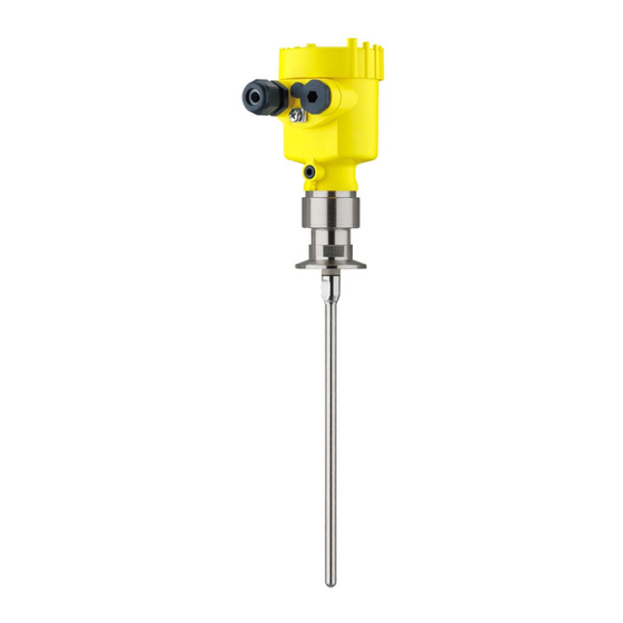
Tdr sensor for continuous level and interface measurement of liquids
Hide thumbs
Also See for VEGAFLEX 83:
- Operating instructions manual (100 pages) ,
- Operating instruction (92 pages) ,
- Quick setup manual (20 pages)

Related Manuals for Vega VEGAFLEX 83


Summary of Contents for Vega VEGAFLEX 83
-
Page 1: Operating Instructions
Operating Instructions TDR sensor for continuous level and interface measurement of liquids VEGAFLEX 83 Foundation Fieldbus Polished rod probe Document ID: 44224... -
Page 2: Table Of Contents
Set up with the quick setup ..................... 49 Saving the parameter adjustment data ................51 Set up with other systems DD adjustment programs ....................52 Field Communicator 375, 475 ..................52 Diagnostics and servicing Maintenance ........................53 VEGAFLEX 83 • Foundation Fieldbus... - Page 3 11.4 Industrial property rights ....................92 11.5 Trademark ........................92 Safety instructions for Ex areas Take note of the Ex specific safety instructions for Ex applications. These instructions are attached as documents to each instrument with Ex approval and are part of the operating instructions manual. Editing status: 2016-04-13 VEGAFLEX 83 • Foundation Fieldbus...
-
Page 4: About This Document
Action This arrow indicates a single action. Sequence of actions Numbers set in front indicate successive steps in a procedure. Battery disposal This symbol indicates special information about the disposal of bat- teries and accumulators. VEGAFLEX 83 • Foundation Fieldbus... -
Page 5: For Your Safety
During work on and with the device the required personal protective equipment must always be worn. Appropriate use VEGAFLEX 83 is a sensor for continuous level measurement. You can find detailed information about the area of application in chapter "Product description". Operational reliability is ensured only if the instrument is properly used according to the specifications in the operating instructions manual as well as possible supplementary instructions. -
Page 6: Namur Recommendations
That is why we have introduced an environment management system with the goal of continuously improving company environmental pro- tection. The environment management system is certified according to DIN EN ISO 14001. Please help us fulfil this obligation by observing the environmental instructions in this manual: • Chapter "Packaging, transport and storage" • Chapter "Disposal" VEGAFLEX 83 • Foundation Fieldbus... -
Page 7: Product Description
Test certificate (PDF) - optional Go to www.vega.com "VEGA Tools" and "Instrument search". Enter the serial number. Alternatively, you can access the data via your smartphone: • Download the smartphone app "VEGA Tools" from the "Apple App Store" or the "Google Play Store" VEGAFLEX 83 • Foundation Fieldbus... -
Page 8: Principle Of Operation
– If necessary, further certificates Principle of operation Application area The VEGAFLEX 83 is a level sensor with polished rod probe for continuous level or interface measurement, particularly suitable for applications in the food processing and pharmaceutical industry. Optionally an autoclaved version with separable housing is available. - Page 9 Functional principle - in- High frequency microwave impulses are guided along a steel cable or terface measurement rod. Upon reaching the product surface, a part of the microwave im- pulses is reflected. The other part passes through the upper product and is reflected by the interface. The running times to the two product layers are processed by the instrument. VEGAFLEX 83 • Foundation Fieldbus...
- Page 10 Example: upper medium dielectric constant 2, lower medium at least dielectric constant 12. Gas phase (L3) • Air or gas mixture • Gas phase - dependent on the application, gas phase does not always exist (d2 = 0) VEGAFLEX 83 • Foundation Fieldbus...
-
Page 11: Packaging, Transport And Storage
The interface adapter VEGACONNECT enables the connection of communication-capable instruments to the USB interface of a PC. For parameter adjustment of these instruments, the adjustment software PACTware with VEGA-DTM is required. You can find further information in the operating instructions "Interface adapter VEGACONNECT" (Document-ID 32628). VEGAFLEX 83 • Foundation Fieldbus... - Page 12 3 Product description The VEGADIS 81 is an external display and adjustment unit for VEGA VEGADIS 81 plics sensors. ® For sensors with double chamber housing the interface adapter "DISADAPT" is also required for VEGADIS 81. You can find further information in the operating instructions "VE- GADIS 81" (Document-ID 43814).
- Page 13 3 Product description You can find additional information in the operating instructions manual "External housing" (Document-ID 46802). Centering If you mount the VEGAFLEX 83 in a bypass tube or standpipe, you have to avoid contact to the bypass tube by using a spacer at the probe end. You can find additional information in the operating instructions manual "Centering".
-
Page 14: Mounting
"Technical data" as well as on the type label. Mounting instructions Installation position Mount VEGAFLEX 83 in such a way that the distance to vessel instal- lations or to the vessel wall is at least 300 mm (12 in). In non-metallic VEGAFLEX 83 • Foundation Fieldbus... - Page 15 The guided microwave principle requires a metallic surface on the process fitting. Therefore, in plastic vessels, etc., use an instru- ment version with flange (from DN 50) or place a metal sheet (ø > 200 mm/8 in) beneath the process fitting when screwing it in. Make sure that the plate has direct contact with the process fitting. When installing rod or cable probes in vessels without metal walls, e.g. in plastic vessels, the measured value can be influenced by strong electromagnetic fields (emitted interference according to EN 61326: class A). In this case, use a probe with coaxial version. VEGAFLEX 83 • Foundation Fieldbus...
- Page 16 In such cases, always carry out a false signal suppression after instal- lation. You can find further information under "Setup procedure". DN25 ... DN150 ≤ 150 mm ( 5.91") > DN150 ... DN200 ≤ 100 mm ( 3.94") Fig. 6: Mounting socket When welding the socket, make sure that the socket is flush with the vessel top. VEGAFLEX 83 • Foundation Fieldbus...
- Page 17 - measurement in these areas is not possible (dead band). The length of the cable can be used all the way to the end only when measuring conductive VEGAFLEX 83 • Foundation Fieldbus...
- Page 18 For this, use an additional plastic sleeve (PTFE, PPS, PEEK etc.), to protect the probe against damages. Keep in mind that below the fastening, a measurement is not possible. Fig. 9: Fasten the probe Measuring probe Retaining sleeve 3 Plastic sleeve (PTFE, PPS, PEEK etc.) VEGAFLEX 83 • Foundation Fieldbus...
- Page 19 Screw the enclosed lid with slotted nut onto the instrument side of the process fitting and tighten the nut with a torque of 20 Nm. Make sure that no liquid or contamination penetrates into the housing or the process side. After autoclaving, screw the lid off again and place the housing verti- cally on the side of the process fitting. Tighten the slotted nut with a torque of 20 Nm. VEGAFLEX 83 • Foundation Fieldbus...
- Page 20 ø w ø w DIN DN25 DN32 DN40 / 1" 1 1/2" ø 50,5 DIN DN50 / 2" ø 64 DIN DN65 / 3" ø 91 Fig. 10: Autoclaved version 1 Groove nut 2 Process fitting 3 Cover with groove nut VEGAFLEX 83 • Foundation Fieldbus...
-
Page 21: Connecting To Power Supply
In systems with potential equalisation, connect the cable screen directly to ground potential at the power supply unit, in the connection box and at the sensor. The screen in the sensor must be connected VEGAFLEX 83 • Foundation Fieldbus... -
Page 22: Connecting
4. Remove approx. 10 cm (4 in) of the cable mantle, strip approx. 1 cm (0.4 in) of insulation from the ends of the individual wires 5. Insert the cable into the sensor through the cable entry Fig. 11: Connection steps 5 and 6 - Single chamber housing VEGAFLEX 83 • Foundation Fieldbus... -
Page 23: Wiring Plan, Single Chamber Housing
10. Reinsert the display and adjustment module, if one was installed 11. Screw the housing lid back on The electrical connection is finished. Wiring plan, single chamber housing The following illustration applies to the non-Ex, Ex-ia and Ex-d-ia version. VEGAFLEX 83 • Foundation Fieldbus... -
Page 24: Wiring Plan, Double Chamber Housing
The following illustrations apply to the non-Ex as well as to the Ex-ia version. Electronics compartment 6 7 8 Fig. 14: Electronics compartment, double chamber housing Internal connection to the terminal compartment 2 Contact pins for the display and adjustment module or interface adapter Simulation switch ("1" = mode for simulation release) VEGAFLEX 83 • Foundation Fieldbus... - Page 25 Parallel use of an external display and adjustment unit and a display and adjustment module in the terminal compartment is not supported. Terminal compartment - Radio module PLICS- MOBILE Status SIM-Card Test Fig. 16: Terminal compartment, radio module PLICSMOBILE Voltage supply You can find detailed information on connection in the supplementary instructions "PLICSMOBILE GSM/GPRS radio module". VEGAFLEX 83 • Foundation Fieldbus...
-
Page 26: Double Chamber Housing With Disadapt
Fig. 18: View to the plug connector M12 x 1 Pin 1 Pin 2 Pin 3 Pin 4 Contact pin Colour connection ca- Terminal, electronics ble in the sensor module Pin 1 Brown Pin 2 White Pin 3 Blue Pin 4 Black VEGAFLEX 83 • Foundation Fieldbus... -
Page 27: Wiring Plan - Version Ip 66/Ip 68, 1 Bar
Voltage supply You can find detailed information on connection in the supplementary instructions "PLICSMOBILE GSM/GPRS radio module". Switch-on phase After VEGAFLEX 83 is connected to the bus system, the instrument carries out a self-test for approx. 30 seconds. The following steps are carried out: • Internal check of the electronics •... -
Page 28: Set Up With The Display And Adjustment Module
The display and adjustment module is powered by the sensor, an ad- ditional connection is not necessary. Fig. 21: Installing the display and adjustment module in the electronics compart- ment of the single chamber housing VEGAFLEX 83 • Foundation Fieldbus... -
Page 29: Adjustment System
In the terminal compartment Note: If you intend to retrofit the instrument with a display and adjustment module for continuous measured value indication, a higher lid with an inspection glass is required. Adjustment system Fig. 23: Display and adjustment elements 1 LC display Adjustment keys • Key functions [OK] key: VEGAFLEX 83 • Foundation Fieldbus... - Page 30 [OK] will not be saved. Switch-on phase After switching on, the VEGAFLEX 83 carries out a short self-test where the device software is checked. The output signal transmits a fault signal during the switch-on phase. The following information is displayed on the display and adjustment module during the startup procedure: •...
-
Page 31: Parameter Adjustment - Quick Setup
Display: Language setting, settings for the measured value indication as well as lighting Diagnosis: Information, e.g. on instrument status, pointer, measure- ment certainty, simulation, echo curve Additional adjustments: e.g. date/time, reset, copy sensor data VEGAFLEX 83 • Foundation Fieldbus... - Page 32 Setup - Application - Ap- In this menu item, you can select the application. You can choose plication between level measurement and interface measurement. You can also choose between measurement in a vessel or in a bypass or standpipe. VEGAFLEX 83 • Foundation Fieldbus...
- Page 33 This menu item is only available if you have selected interface meas- electric constant urement under the menu item "Application". In this menu item you can choose the type of medium of the upper medium. VEGAFLEX 83 • Foundation Fieldbus...
- Page 34 Adjust the requested percentage value with [+] and store with [OK]. Enter the suitable distance value in m for the empty vessel (e.g. distance from the flange to the probe end) corresponding to the per- centage value. The distance refers tot he sensor reference plane (seal surface of the process fitting). VEGAFLEX 83 • Foundation Fieldbus...
- Page 35 A false signal suppression detects, marks and saves these false signals so that they are no longer taken into account for the level and interface measurement. We generally recommend carrying out a false signal suppression to achieve the best possible accuracy. This should VEGAFLEX 83 • Foundation Fieldbus...
- Page 36 "Application", you can adjust the damping for the level and the inter- face separately. The default setting is a damping of 0 s. Setup - Linearization A linearization is necessary for all vessels in which the vessel volume does not increase linearly with the level - e.g. a horizontal cylindri- cal or spherical tank, when the indication or output of the volume is VEGAFLEX 83 • Foundation Fieldbus...
- Page 37 For the socket correction you have to enter the height of the socket above the upper edge of the vessel. If the socket is lower than the up- per edge of the vessel, this value can also be negative. VEGAFLEX 83 • Foundation Fieldbus...
- Page 38 PIN is activated/deactivated permanently. With active PIN, only the following adjustment functions are possible without entering a PIN: • Select menu items and show data • Read data from the sensor into the display and adjustment mod- ule. VEGAFLEX 83 • Foundation Fieldbus...
- Page 39 Display - Displayed value In this menu item, you define the indication of the measured value on the display. You can display two different measured values. In this menu item, you define measured value 2. The default setting for the displayed value 2 is the electronics tem- perature. Display - Backlight The integrated background lighting can be switched off via the adjustment menu. The function depends on the strength of the supply voltage, see "Technical data". VEGAFLEX 83 • Foundation Fieldbus...
- Page 40 "Setup - Application", the peak values of the interface measurement are displayed in addition to the peak values of the level measurement. In another window you can carry out a reset of the two peak values separately. VEGAFLEX 83 • Foundation Fieldbus...
- Page 41 This allows the signal path to be tested, e.g. through down- stream indicating instruments or the input card of the control system. To activate the simulation, you have to set the simulation switch on the electronics module to 1. VEGAFLEX 83 • Foundation Fieldbus...
- Page 42 With the adjustment software PACTware and the PC the high-reso- lution echo curve can be displayed and used later on to assess the quality of the measurement. Additional adjustments - In this menu item, the internal clock of the sensor is adjusted. Date/Time VEGAFLEX 83 • Foundation Fieldbus...
- Page 43 Max. adjustment - Level Distance: 0.000 m(d) - note block- ing distances Min. adjustment - Level Min. adjustment - Level Distance: Probe length - take dead band into account Accept adjustment of the level measurement? VEGAFLEX 83 • Foundation Fieldbus...
- Page 44 Device memory - Measured value memory - Start Not active with measured value Device memory - Measured value memory - Stop Not active with measured value Device memory - Measured value memory - Stop Not active recording when memory is full VEGAFLEX 83 • Foundation Fieldbus...
- Page 45 This is necessary to adapt the electronics optimally to the probe. Additional adjustments - In this menu item you gain access to the protected area where Special parameters you can enter special parameters. In exceptional cases, individual parameters can be modified in order to adapt the sensor to special requirements. VEGAFLEX 83 • Foundation Fieldbus...
-
Page 46: Saving The Parameter Adjustment Data
The procedure is described in the menu "Additional adjust- ments" in the menu item "Copy sensor data". The data remain there permanently even if the sensor power supply fails. VEGAFLEX 83 • Foundation Fieldbus... - Page 47 If it is necessary to exchange a sensor, the display and adjustment module is inserted into the replacement instrument and the data are likewise written into the sensor via the menu item "Copy sensor data". VEGAFLEX 83 • Foundation Fieldbus...
-
Page 48: Setup With Pactware
Further setup steps are described in the operating instructions manu- al "DTM Collection/PACTware" attached to each DTM Collection and which can also be downloaded from the Internet. Detailed descrip- tions are available in the online help of PACTware and the DTMs. VEGAFLEX 83 • Foundation Fieldbus... -
Page 49: Set Up With The Quick Setup
The standard version is available as a download under www.vega.com/downloads and "Software". The full version is avail- able on CD from the agency serving you. Set up with the quick setup... - Page 50 2 Extended adjustment Maintenance Quick setup With quick setup you can carry out the parameter adjustment of VEGAFLEX 83 for your application in just a few simple steps. The assistant-driven adjustment includes the basic settings for simple, reliable setup and commissioning. Information: If the function is inactive, then possibly no instrument is connected.
-
Page 51: Saving The Parameter Adjustment Data
7 Setup with PACTware Saving the parameter adjustment data We recommend documenting or saving the parameter adjustment data via PACTware. That way the data are available for multiple use or service purposes. VEGAFLEX 83 • Foundation Fieldbus... -
Page 52: Set Up With Other Systems
This software is updated via the Internet and new EDDs are automatically taken over into the device catalogue of this software after they are released by the manufacturer. They can then be transferred to a Field Communicator. VEGAFLEX 83 • Foundation Fieldbus... -
Page 53: Diagnostics And Servicing
Echo curve of the setup: This is used as reference echo curve for the measurement conditions during setup. Changes in the measure- ment conditions during operation or buildup on the sensor can thus be recognized. The echo curve of the setup is stored via: • PC with PACTware/DTM VEGAFLEX 83 • Foundation Fieldbus... -
Page 54: Status Messages
This status message is inactive by default. It can be activated by the user via PACTware/DTM or EDD. Out of specification: The measured value is unstable because the instrument specification is exceeded (e.g. electronics temperature). This status message is inactive by default. It can be activated by the user via PACTware/DTM or EDD. Maintenance: Due to external influences, the instrument function is limited. The measurement is affected, but the measured value is VEGAFLEX 83 • Foundation Fieldbus... - Page 55 F041 – Cable probe broken or – Check probe and Bit 13 rod probe defective exchange, if neces- Probe loss sary F080 – General software error – Briefly separate oper- Bit 5 ating voltage General software error VEGAFLEX 83 • Foundation Fieldbus...
- Page 56 – Check operating Bit 14 voltage voltage Imper- – Check connection missible cables operating voltage F267 – Sensor cannot start – Exchanging the elec- tronics No execut- – Send instrument for able sensor repair software VEGAFLEX 83 • Foundation Fieldbus...
- Page 57 – If necessary, increase missible operating voltage operating voltage Maintenance The following table shows the error codes and text messages in the status message "Maintenance" and provides information on causes as well as corrective measures. VEGAFLEX 83 • Foundation Fieldbus...
-
Page 58: Rectify Faults
The operator of the system is responsible for taking suitable meas- tion occurs ures to rectify faults. Procedure for fault recti- The first measures are: fication • Evaluation of fault messages, for example via the display and adjustment module • Checking the output signal VEGAFLEX 83 • Foundation Fieldbus... - Page 59 – Amplitude or position of a – Determine the reason for the false signal has changed (e.g. changed false signals, carry out buildup); false signal suppres- false signal suppression, e.g. sion no longer matches with buildup VEGAFLEX 83 • Foundation Fieldbus...
- Page 60 • Constant level • Filling • Emptying The images in column "Error pattern" show the real level as a broken line and the level displayed by the sensor as a continuous line. VEGAFLEX 83 • Foundation Fieldbus...
- Page 61 – Amplitude or position of a false – Determine the reason for the signal has changed (e.g. con- changed false signals, carry out densation, buildup); false signal false signal suppression, e.g. suppression no longer matches with condensation actual conditions VEGAFLEX 83 • Foundation Fieldbus...
- Page 62 – In case of interferences due to installations in the close range: Change polarisation direction – After eliminating the false sig- nals, the false signal suppres- sion must be deleted. Carry out a new false signal suppression VEGAFLEX 83 • Foundation Fieldbus...
-
Page 63: Exchanging The Electronics Module
24 hour service hotline Should these measures not be successful, please call in urgent cases the VEGA service hotline under the phone no. +49 1805 858550. The hotline is also available outside normal working hours, seven days a week around the clock. -
Page 64: Exchanging The Rod
4. Screw the new rod carefully by hand onto the thread on the pro- cess fitting. 5. Exert counterforce manually and tighten the rod on the flat sur- faces with a torque of 4.5 Nm (3.32 lbf ft). Fig. 47: Exchanging the measuring rod Seal ring Information: Please maintain the specified torque so that the max. tensile strength of the connection remains. VEGAFLEX 83 • Foundation Fieldbus... -
Page 65: Exchanging The Seal
Use special tools in order to avoid damag- ing the surface. 1. Loosen the rod by applying a fork spanner to the flat surfaces (SW 10), provide counterforce manually on the process fitting 2. Screw out the loosened measuring rod by hand 3. Push the enclosed new seal ring (9.25 x 1.78) onto the thread of the measuring rod. VEGAFLEX 83 • Foundation Fieldbus... - Page 66 9 Diagnostics and servicing Fig. 48: Exchanging the measuring rod Sealing ring (9.25 x 1.78) 4. Loosen process fitting with a suitable wrench. 5. Unscrew the process fitting manually from the sensor. 6. Remove the old seal out of the process fitting. 7. Insert the attached new seal ring (15.54 x 2.62) into the process fitting. VEGAFLEX 83 • Foundation Fieldbus...
-
Page 67: Software Update
4.5 Nm (3.32 lbf ft). Information: Please maintain the specified torque so that the max. tensile strength of the connection remains. Software update The following components are required to update the instrument software: • Instrument • Voltage supply • Interface adapter VEGACONNECT • PC with PACTware • Current instrument software as file VEGAFLEX 83 • Foundation Fieldbus... -
Page 68: How To Proceed If A Repair Is Necessary
Clean the instrument and pack it damage-proof • Attach the completed form and, if need be, also a safety data sheet outside on the packaging • Please contact the agency serving you to get the address for the return shipment. You can find the agency on our home page www.vega.com. VEGAFLEX 83 • Foundation Fieldbus... -
Page 69: Dismount
Pass the instrument directly on to a spe- cialised recycling company and do not use the municipal collecting points. These may be used only for privately used products according to the WEEE directive. VEGAFLEX 83 • Foundation Fieldbus... -
Page 70: Supplement
Ʋ Rod: ø 8 mm (0.315 in) - polished up to 4 m (13.12 ft) - also possible for segmented rods Ʋ Trimming accuracy - rod ±1 mm + 0.05 % of the rod length All wetted parts VEGAFLEX 83 • Foundation Fieldbus... - Page 71 ø 1 m (3.281 ft), centric installation, process fitting flush with the vessel ceiling Ʋ Medium Water/Oil (dielectric constant ~2.0) Ʋ Installation Probe end does not touch the vessel bottom Sensor parameter adjustment No gating out of false signals carried out With interface measurement = 2.0 VEGAFLEX 83 • Foundation Fieldbus...
- Page 72 Lower dead band (see following diagrams - grey section) Typical deviation - Interface measure- ± 5 mm (0.197 in) ment Typical deviation - Total level interface See following diagrams measurement Typical deviation - Level measurement See following diagrams 3)4) Depending on the installation conditions, deviations can occur which can be rectified by adapting the adjust- ment or changing the measured value offset in the DTM service mode The dead bands can be optimized via a false signal suppression. VEGAFLEX 83 • Foundation Fieldbus...
- Page 73 Temperature drift - Digital output ±3 mm/10 K relating to the max. measuring range or max. 10 mm (0.394 in) Additional deviation through electromag- < ±10 mm (< ±0.394 in) netic interference acc. to EN 61326 VEGAFLEX 83 • Foundation Fieldbus...
- Page 74 Process temperature (Clamp or flange temperature) Ʋ FFKM (Kalrez 6621) -20 … +150 °C (-4 … +302 °F) Time span after a sudden measuring distance change by max. 0.5 m in liquid applications, max 2 m with bulk solids applications, until the output signal has taken for the first time 90 % of the final value (IEC 61298-2). VEGAFLEX 83 • Foundation Fieldbus...
- Page 75 Options of the cable entry Ʋ Cable entry M20 x 1.5, ½ NPT Ʋ Cable gland M20 x 1,5; ½ NPT (cable ø see below table) Ʋ Blind plug M20 x 1.5; ½ NPT Ʋ Closing cap ½ NPT VEGAFLEX 83 • Foundation Fieldbus...
- Page 76 W x H = 7 x 13 mm Adjustment elements 4 keys Protection rating Ʋ unassembled IP 20 Ʋ mounted in the housing without lid IP 40 Materials Ʋ Housing Ʋ Inspection window Polyester foil VEGAFLEX 83 • Foundation Fieldbus...
- Page 77 Single chamber IP 66/IP 68 (0.2 bar) Type 6P IP 68 (1 bar) Type 6P Double chamber IP 66/IP 67 Type 4X IP 66/IP 68 (0.2 bar) Type 6P IP 68 (1 bar) Type 6P VEGAFLEX 83 • Foundation Fieldbus...
-
Page 78: Supplementary Information Foundation Fieldbus
Instruments with approvals can have different technical specifications depending on the version. For that reason the associated approval documents of these instruments have to be carefully noted. They are part of the delivery or can be downloaded under www.vega.com, "VEGA Tools" and "Instrument search" as well as in the download area. 11.2 Supplementary information Foundation Fieldbus The following table gives you an overview of the instrument versions and the corresponding device descriptions, the electrical characteristics of the bus system as well as the applied function blocks. - Page 79 Value 1 Value Fig. 54: Schematic presentation Transducer Block (TB) Function block Analog Input (AI) The function block "Analog Input (AI)" takes the original measured value selected by a Channel Number and makes it available to additional function blocks on its output. VEGAFLEX 83 • Foundation Fieldbus...
- Page 80 Fig. 56: Schematic presentation function block Discret Input (DI) Function block PID Control The function block "PID Control " is a key component for various tasks in the process automation and is used universally. PID blocks can be cascaded if this is necessary or requested due to differ- ent time constants with the primary and secondary process measurement. Fig. 57: Schematic presentation function block PID Control VEGAFLEX 83 • Foundation Fieldbus...
- Page 81 The function block "Integrator" integrates a continuous input signal over the time and sums the results of an impulse input block. It is used as a totalizer up to a reset or as a subtotalizer up to a reference point at which the integrated and accumulated value is compared with the default values. When these default values are reached, digital output signals will be outputted. The integration func- tion is carried out upwardly starting with zero and downwards with a default value. Two flow values are also available so that the net flow volume can be calculated and integrated. This can be used for calculation of volume and mass changes in the vessel or for optimisation of flow controls. VEGAFLEX 83 • Foundation Fieldbus...
- Page 82 The function block "Arithmetic" allows the simple integration of usual metrological calculation func- tions. The user can select the requested measurement algortihm according to the name without known the formula. The following algorithms are available: • Flow compensation, linear • Flow compensation, square root VEGAFLEX 83 • Foundation Fieldbus...
- Page 83 Selected unit code for "SECONDARY_VALUE_1" UNIT SECONDARY_VALUE_2 This is the distance value ("sensor_value") with the status of the transducer block. The unit is defined in "SECONDARY_VAL- UE_2_UNIT" FILL_HEIGHT_VALUE Filling height. The unit is defined in "FILL_HEIGHT_VALUE_ UNIT" FILL_HEIGHT_VALUE_UNIT Filling height unit CONST_VALUE Constant value SECONDARY_VALUE_1_ Secondary value 1 type TYPE VEGAFLEX 83 • Foundation Fieldbus...
- Page 84 0 % and 100 % curve in near and far range FALSE_SIGNAL_CMD_CON- Gradient of the manual sectors, safety at the end of false echo FIGURATION2 memory and depending on the import range gating out the false signals VEGAFLEX 83 • Foundation Fieldbus...
- Page 85 Min.-/max.- values of electronics temperature, date USER_MIN_MAX_PHYSI- Min.-/max.- distance values, date CAL_VALUE RESET_PEAK_PHYSICAL_ VALUE RESET_LINEARIZATION_ CURVE DEVICE_STATUS_ASCII Device status ECHO_CURVE_PLICSCOM_ Parameters as curve selection and resolution REQUEST ECHO_CURVE_PLICSCOM_ Parameters as start and end LIMITS APPROVAL_WHG Sensor acc. to WHG VEGAFLEX 83 • Foundation Fieldbus...
-
Page 86: Dimensions
TYPE ECHO_MEM_STATE Busy, curve type, error code 11.3 Dimensions The following dimensional drawings represent only an extract of all possible versions. Detailed dimensional drawings can be downloaded at www.vega.com/downloads under "Drawings". Plastic housing ~ 69 mm ~ 84 mm (2.72") (3.31") - Page 87 Aluminium housing with protection rating IP 66/IP 68 (1 bar) ~ 105 mm ~ 150 mm (4.13") (5.91") ø 86 mm ø 86 mm (3.39") (3.39") M16x1,5 M20x1,5 M20x1,5 M20x1,5/ ½ NPT Fig. 65: Housing version with protection rating IP 66/IP 68 (1 bar) - with integrated display and adjustment module the housing is 9 mm/0.35 in higher Single chamber version Double chamber version VEGAFLEX 83 • Foundation Fieldbus...
- Page 88 ø 86 mm ø 80 mm ø 79 mm (3.39") (3.15") (3.11") M16x1,5 M20x1,5 M20x1,5/ ½ NPT M20x1,5/ ½ NPT Fig. 67: Housing version with protection rating IP 66/IP 68 (1 bar) - with integrated display and adjustment module the housing is 9 mm/0.35 in higher Single chamber version, electropolished Single chamber version, precision casting Double chamber version, precision casting VEGAFLEX 83 • Foundation Fieldbus...
- Page 89 11 Supplement VEGAFLEX 83, rod version ø 8 mm (0.315 in), polished ø 8 mm (0.32") Fig. 68: VEGAFLEX 83, rod version ø 8 mm (0.315 in), polished Sensor length, see chapter "Technical data" VEGAFLEX 83 • Foundation Fieldbus...
- Page 90 11 Supplement VEGAFLEX 83, rod version ø 8 mm (0.315 in), polished - autoclaved version ø 54 mm (2.13") ø w ø w DIN DN25 DN32 DN40 / 1" 1 1/2" ø 50,5 DIN DN50 / 2" ø 64 DIN DN65 / 3"...
- Page 91 11 Supplement Extension components - rod extension ø 8 mm (0.315 in), polished SW 10 ø8 mm (0.31") Fig. 70: Extension rods with ø 8 mm (0.315 in) 1 Version with threaded fitting 2 Version with flange connection A Basic extension rod with ø 8 mm (0.315 in) B Extension rod with ø 8 mm (0.315 in) C End rod with ø 8 mm (0.315 in) Length (order length) VEGAFLEX 83 • Foundation Fieldbus...
-
Page 92: Industrial Property Rights
Les lignes de produits VEGA sont globalement protégées par des droits de propriété intellec- tuelle. Pour plus d'informations, on pourra se référer au site www.vega.com. VEGA lineas de productos están protegidas por los derechos en el campo de la propiedad indus- trial. Para mayor información revise la pagina web www.vega.com. - Page 93 – Input Selector 82 – Spacer 13 – Integrator 81 – Output Splitter 81 Reset 43 – PID Control 80 – Signal Characterizer 81 Sensor characteristics 46 – Transducer Block (TB) 79 Sensor status 40 Service hotline 63 VEGAFLEX 83 • Foundation Fieldbus...
- Page 94 INDEX Simulation 41 Special parameters 45 Type label 7 Type of medium 32 Units 32 VEGAFLEX 83 • Foundation Fieldbus...
- Page 95 Notes VEGAFLEX 83 • Foundation Fieldbus...
- Page 96 Subject to change without prior notice © VEGA Grieshaber KG, Schiltach/Germany 2016 VEGA Grieshaber KG Phone +49 7836 50-0 Am Hohenstein 113...
Need help?
Do you have a question about the VEGAFLEX 83 and is the answer not in the manual?
Questions and answers