Table of Contents
Advertisement
Quick Links
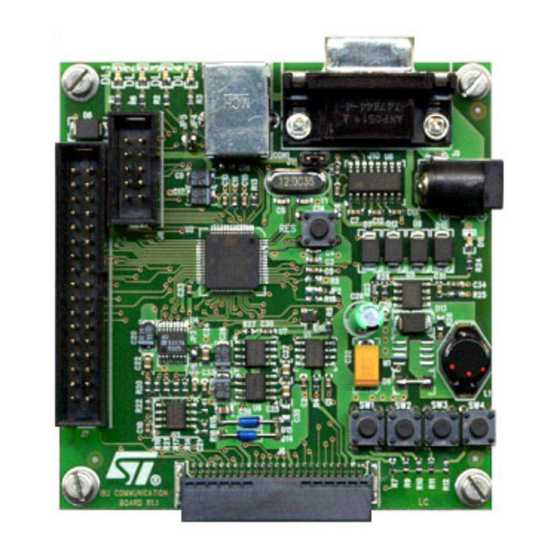
ST Industrial Communication Board - EVALCOMMBOARD
Introduction
ST Industrial Communication Board (order code: EVALCOMMBOARD) is a platform for
Communication, Command and Control exchange with Industrial reference design boards.
Its goal is to provide ST Industrial customers a reliable and easily accessible communication
channel, between a controlling PC and Industrial reference design boards.
It is a unique platform that allows evaluating a wide range of Industrial products in their
application environment.
Application fields covered by this platform are:
●
Power line communication
●
Motor control and gate driving
●
Intelligent power switches
Industrial Communication Board
June 2006
Rev 1
UM0240
User manual
www.st.com
1/39
Advertisement
Table of Contents

Related Manuals for ST EVALCOMMBOARD


Summary of Contents for ST EVALCOMMBOARD
- Page 1 ST Industrial Communication Board (order code: EVALCOMMBOARD) is a platform for Communication, Command and Control exchange with Industrial reference design boards. Its goal is to provide ST Industrial customers a reliable and easily accessible communication channel, between a controlling PC and Industrial reference design boards.
-
Page 2: Table Of Contents
Contents UM0240 Contents System overview ..........6 Power supply . - Page 3 UM0240 Contents 10.1 Device firmware upgrade ........26 10.2 Applications .
- Page 4 ST motor control evaluation boards ........
- Page 5 UM0240 List of figures List of figures Figure 1. Main power supply ............8 Figure 2.
-
Page 6: System Overview
Jumpers, switches and LEDs give further adaptability and visualization tools. A full range of dedicated FW, GUIs and reference design boards are available for every ST Industrial product, fully compatible with the ST Industrial Communication Board. 6/39... -
Page 7: Power Supply
UM0240 Power supply Power supply Board components require the following voltage supplies. Table 1. Voltages present on board Function Supply Converter Device Input Range Output Value Switching Main Power Converter L5973D 5V ÷ 35V Supply (Buck) Regulated MCU Flash Charge Pump ST662A (pin VOUT) Programming Converter... -
Page 8: Figure 1. Main Power Supply
Power supply UM0240 Figure 1. Main power supply 8/39... -
Page 9: Figure 2. Flash Programming And Opamp Power Supply
UM0240 Power supply Figure 2. Flash programming and OpAmp power supply 9/39... -
Page 10: Main Power Supply (Vdd)
In-Application Programming (IAP) of the embedded Flash memory. This power supply consists in a charge pump DC-DC regulator implemented by the ST device ST662A, which is a step-up converter designed for the Flash memory programming. -
Page 11: Opamp Negative Supply (-5V)
UM0240 Power supply The connection between the charge pump output and the Vpp line is switched by the P- MOS STS5DPF20L controlled by pin PF1 of the microcontroller. This separates the IAP and In-Circuit Programming (ICP) and delivers V with a shorter rising time. -
Page 12: Microcontroller
Microcontroller UM0240 Microcontroller Microcontroller features The board is based on the ST72F651AR6 USB microcontroller, its mains features are: ● Up to 8MHz ST7 control unit ● 32 KBytes embedded Flash program memory ● 5 KBytes embedded RAM memory ● UVLO ●... -
Page 13: 10-Bit Digital-To-Analog Converter (Dac)
UM0240 10-bit digital-to-analog converter (DAC) 10-bit digital-to-analog converter (DAC) The Industrial Communication Board embeds a 10(12)-bit buffered voltage-output DAC implemented by the AD5317 (AD5327) converter from Analog Devices. The IC provides four buffered rail-to-rail outputs, in the range 0 ÷ Vcc, with a slew rate of 0.7 V/µs. The DAC is controlled by the Microcontroller (PC2, PC3, PC4) through a 3-wires serial interface and is compatible with SPI, QSPI, MICROWIRE and DSP interface standards. -
Page 14: Operational Amplifiers (Opamp)
Operational amplifiers (OpAmp) UM0240 Operational amplifiers (OpAmp) The LM358 consists of two independent, high gain (100 dB), high bandwidth (1.1 MHz) and internally compensated operational amplifiers. In the Industrial Communication Board the two amplifiers are designed in differential configuration, with a bipolar power supply 5V ÷ - 5V. -
Page 15: Interfaces And Connectors
UM0240 Interfaces and connectors Interfaces and connectors The ST Industrial Communication Board has 6 connectors to interface with power supply (J9), Personal Computer (CON1 and J10), In Circuit Communication (J8) and ST Devices Evaluation Boards (J6 and J7). Figure 4. -
Page 16: Usb
Interfaces and connectors UM0240 Figure 5. Industrial Communication Board connectors pcb The main communication channel with the controlling PC is through the ST72F651 Full Speed USB interface, based on a Vendor Specific Class embedded in the Industrial Communication Board firmware and a dedicated driver, part of the controlling software. Once the USB cable is plugged to connector CON1, the Industrial Communication Board takes its power supply from the 5V USB interface of the PC. -
Page 17: Rs-232 Interface
UM0240 Interfaces and connectors RS-232 Interface The RS-232 interface can be used as a communication channel to a PC running control software. It consists of female connector J10, where only three pins are connected with the DCE connections: 5 → Ground ●... -
Page 18: Power Line Communication
Interfaces and connectors UM0240 Table 2. Motor control interface pins (continued) Pin number Signal name Description Generated by Ch A Input 2 Ch B Enable Signal Power line communication The board can communicate with a Power Line Communication Board through its 50-pin J6 connector providing four kinds of signals: digital signals, analog signals, control signals and power signals. -
Page 19: In-Circuit Communication
Power supply As described in Section 2: Power supply, the ST Industrial Communication Board can take is power supply from different sources. If an external dedicated power supply is selected, it must be in the 5V ÷ 35V range. Taking into account that the board has a power consumption in steady state of approximately 50mW, a value of 500mW is suggested. -
Page 20: Figure 7. Industrial Communication Board Jumpers And Switches On Pcb
Interfaces and connectors UM0240 Figure 7. Industrial Communication Board jumpers and switches on PCB Jumper JP2 connects the ST72F651 reset pin to a reset signal coming from the PLM board. This is used to reset the MCU after a Power Line Modem reset event. Setting: ●... - Page 21 UM0240 Interfaces and connectors Setting: ● Open = for ICC use ● Closed = for LEDs use Jumper J11 disconnects the RS-232 level shifter from the power supply. This reduces power consumption if the RS-232 interface is not used and frees MCU pins for another use.
-
Page 22: Switches
Switches UM0240 Switches The board is equipped with five switches: a microcontroller reset switch (RES), and four general purpose switches (SW1, SW2, SW3 and SW4). The RES switch is directly connected with the microcontroller RESET pin used to perform a hardware reset of the MCU. -
Page 23: Leds
UM0240 LEDs LEDs Five LEDs are present on the board for visual communication with the user. DL1, DL2, DL3, DL4 are general purpose LEDs that are User Application configurable. LED D11 is power supply (5V) on indicator. Figure 10. Industrial Communication Board leds on PCB 23/39... -
Page 24: Applications
Applications UM0240 Applications The ST Industrial Communication Board is designed to be a general purpose control board for all Industrial applications. Currently two application fields are supported: Power Line Communication and Motor Control. Soon Intelligent Power Switch and Gate Driver applications will be covered too. -
Page 25: Motor Control
Both PLC Reference Design boards include a Power Supply section, specifically tailored for matching Power Line coupling requirements, and a Transceiver section designed around the ST PLC chipset, including a 16-MHz crystal oscillator and an external passive coupling filter for impedance adapting and noise filtering. -
Page 26: Firmware
Firmware UM0240 Firmware The ST Industrial Communication Board FirmWare provides two main functions: Upgrading the on-board firware stored in the Flash memory Providing application-specific code that enables communication with different application boards 10.1 Device firmware upgrade The DFU (Device Firmware Upgrade) feature enables the user to upgrade the application- specific firmware on the Industrial Communication Board through the PC USB port. -
Page 27: Applications
UM0240 Firmware 10.2 Applications Beside the DFU, application-specific firmware has been developed to enable the Industrial Communication Board to control and communicate with different application boards. 10.2.1 Power Line Communication (PLC) Dedicated firmware is available to use in conjunction with Power Line Communication (PLC) Boards. -
Page 28: Software
11.1 PLC ST7538/40 DEMOKIT software evaluation tool The "ST7538/40 DEMOKIT Software Evaluation Tool" allows interfacing one or more ST Power Line Modem Demo Boards with a Personal Computer. Supported Demo Boards are those equipped with devices ST7538 and ST7540. The Software automatically recognizes which type of device is connected to the PC and looks slightly different depending on the connected device. -
Page 29: Figure 16. The Main Window
UM0240 Software Figure 16. The main window P RO G RA M SECTIO NS: M EN U B AR TO O LB AR STA TUS BA R Through the Main Window it is possible to access all software functions. Four different panels are available: ●... -
Page 30: Motor Control
Software UM0240 sends a sequence of messages to one or more Slaves. If the messages are correctly received from Slaves, they are re-sent to the Master. 11.2 Motor control Motor Control FW loaded on Industrial Communication Board can be accessed by the user through a dedicated GUI. -
Page 31: Figure 18. Dc Motor Driving Gui
UM0240 Software The control panel allows the user to set the current, as a percentage of the maximum value determined by the hardware, for each portion of the movement and the holding time. When motor settings have been defined one can start and stop the motor by simply clicking on the RUN and STOP. -
Page 32: Appendix
Appendix UM0240 Appendix 12.1 Reference ● Datasheets: – ST232 5V Powered Multi-channel RS-232 Drivers and Receivers – STS4DPF20L Dual P-channel 20V - 0.07 W - 4A SO-8 STripFET™ Power MOSFET – LM158,A-LM258,A, LM358, A Low Power Dual Operational Amplifiers – AD5307/AD5317/AD5327 8-/10-/12-Bit DACs –... -
Page 33: Schematics
UM0240 Appendix 12.2 Schematics Figure 20. Industrial Communication Board 33/39... -
Page 34: Figure 21. Power Supply
Appendix UM0240 Figure 21. Power supply 34/39... -
Page 35: Pcb
UM0240 Appendix 12.3 Figure 22. Industrial Communication Board and power supply 12.4 Bill of materials Table 8. Bil of materials Reference Description CON1 Molex Connector 67068 USB tipe B C1:C7, C10:C13, C15, C16, C18, C19, C21, C23, C29, Ceramic Capacitor 100nF 50V 0603 C30, C41 35/39... -
Page 36: Table 8
Appendix UM0240 Table 8. Bil of materials (continued) Reference Description Ceramic Capacitor 22nF 50V 0603 C8, C14 Ceramic Capacitor 47pF 50V 0603 C9, C17, C26, C33 Tantalum Capacitor 4,7uF 16V 3528 Tantalum Capacitor 10uF 16V 3528 C22, C24, C36 Ceramic Capacitor 1uF 16V 0805 C25, C27 Ceramic Capacitor 220nF 16V... - Page 37 UM0240 Appendix Table 8. Bil of materials (continued) Reference Description Resistance 300K 1% 0603 Resistance 1K5 1% 0603 R14, R15, R17:R22, R27 Resistance 10K 1% 0603 Resistance 8K25 1% 0603 Resistance 2K7 0603 SW1:SW5 Button U1, U7 STS5DPF20L ST72F651 TQFP LM358 AD5317 TSSOP...
-
Page 38: Revision History
Revision history UM0240 Revision history Table 9. Revision history Date Revision Changes 28-Jun-2006 Initial release. 38/39... - Page 39 No license, express or implied, by estoppel or otherwise, to any intellectual property rights is granted under this document. If any part of this document refers to any third party products or services it shall not be deemed a license grant by ST for the use of such third party products or services, or any intellectual property contained therein or considered as a warranty covering the use in any manner whatsoever of such third party products or services or any intellectual property contained therein.
Need help?
Do you have a question about the EVALCOMMBOARD and is the answer not in the manual?
Questions and answers