Table of Contents
Advertisement
UM2846
User manual
EVAL-L9963E-MCU evaluation board
Introduction
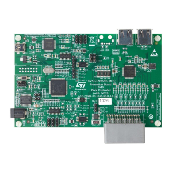
The EVAL-L9963E-MCU is a hardware tool for evaluation and development and is ideal for rapid prototyping of a 48 V battery
management system (BMS) or as lower stage of a distributed BMS. This board can be used to evaluate the features of the
L9963E device and L9963T.
The EVAL-L9963E allows the user to connect up to 14 channels for cell voltage sensing, one channel for current sensing, and
up to 4 channels for temperature sensing (plus an additional on-board NTC to sense PCB temperature). The board provides an
onboard microcontroller with preloaded firmware intended to be used with STSW-L9963E GUI (graphical user interface).
UM2846 - Rev 1 - March 2021
www.st.com
For further information contact your local STMicroelectronics sales office.
Advertisement
Table of Contents

Related Manuals for ST EVAL-L9963E-MCU


Summary of Contents for ST EVAL-L9963E-MCU
- Page 1 Introduction The EVAL-L9963E-MCU is a hardware tool for evaluation and development and is ideal for rapid prototyping of a 48 V battery management system (BMS) or as lower stage of a distributed BMS. This board can be used to evaluate the features of the L9963E device and L9963T.
-
Page 2: Hardware Description
Featured components The EVAL-L9963E-MCU can be considered a reference design for a 48 V BMS or as a first layer of a distributed BMS system. In the following table there is a short description of all the ST featured components. -
Page 3: Board Description
UM2846 Board description Board description Figure 2. Board top view Figure 3. Main components and connectors UM2846 - Rev 1 page 3/23... -
Page 4: Jumpers And Connectors
UM2846 Jumpers and connectors Jumpers and connectors Mother board jumpers and connectors Table 2. Motherboard jumpers and connectors Name Description Type External power supply connector Jack USB connector for PC communication Mini USB connector Isolated serial communication port: 1- VBAT ISOPORT 1 2- ISOH- (From L9963E) USB type A connector... - Page 5 UM2846 Mother board jumpers and connectors Name Description Type 21- cell 3 22- cell 1 23- ground 24- current sensor resistor positive pin Multi pin connector 25- NTC1+ 26- NTC2+ 27- NTC3+ 28- NTC4+ 1-2 ISO- redirected to ISOPORT 1_1 L9963T (U16) ISO- output selection 2-3 ISO- redirected to L9963E 1-2 high amplitude/high threshold...
-
Page 6: Default Jumpers Setting
UM2846 Default jumpers setting Figure 4. P2 Battery connector Default jumpers setting Table 3. Jumpers configuration Name Description Configuration L9963T (U16) ISO- output selection 2-3 ISO- redirected to L9963E L9963T (U16) TX amplitude selection 1-2: high amplitude/high threshold L9963T (U16) SPI master clock selection Unconnected: minimum frequency L9963T (U16) transmitter enable signal Unconnected: controlled by μc (PD9) -
Page 7: Hot Plug Protection
UM2846 Hot plug protection Hot plug protection Figure 5. Hot plug protection circuit The structure shown in the Figure 5 on the GND path will help withstanding the hot plug by limiting the inrush current incoming from any L9963E pin connected to the centralized clamp. Working principle is the following: When L9963E is OFF and no cell is connected, the VTREG regulator is shut down and MHOT is safely kept off by the RPD pull down resistor. -
Page 8: Getting Started
12 V power supply with 2.1 mm jack output, internal pin + • L9963E evaluation GUI (please check STSW-L9963E user manual) EVAL-L9963E-MCU board setup 3.2.1 Low voltage power supply The 12 V power supply must be connected to X1 connector in order to properly supply the low voltage portion of the EVAL-L9963E-MCU board. -
Page 9: L9963E External Connection And Power Supply
UM2846 EVAL-L9963E-MCU board setup 3.2.2 L9963E external connection and power supply Figure 7. L9963E external connection and power supply 3.2.3 Transceiver settings Figure 8. Transceiver settings UM2846 - Rev 1 page 9/23... -
Page 10: Usb To Pc Connection
UM2846 EVAL-L9963E-MCU board setup 3.2.4 USB to PC connection Figure 9. USB to PC connection 3.2.5 Possible connection for battery simulation In case a real battery is not available, it’s possible to use the following circuit to simulate the battery pack. -
Page 11: Board Schematics
UM2846 Board schematics Board schematics Figure 11. Board schematic (1/5) UM2846 - Rev 1 page 11/23... -
Page 12: Figure 12. Board Schematic (2/5)
UM2846 Board schematics Figure 12. Board schematic (2/5) UM2846 - Rev 1 page 12/23... -
Page 13: Figure 13. Board Schematic (3/5)
UM2846 Board schematics Figure 13. Board schematic (3/5) UM2846 - Rev 1 page 13/23... -
Page 14: Figure 14. Board Schematic (4/5)
UM2846 Board schematics Figure 14. Board schematic (4/5) UM2846 - Rev 1 page 14/23... -
Page 15: Figure 15. Board Schematic (5/5)
UM2846 Board schematics Figure 15. Board schematic (5/5) UM2846 - Rev 1 page 15/23... -
Page 16: Board Layout
UM2846 Board layout Board layout Figure 16. Assembly top Figure 17. Inner 1 UM2846 - Rev 1 page 16/23... -
Page 17: Figure 18. Inner 2
UM2846 Board layout Figure 18. Inner 2 Figure 19. Assembly bottom UM2846 - Rev 1 page 17/23... -
Page 18: Internal And External Communication Configuration
UM2846 Internal and external communication configuration Internal and external communication configuration Figure 20. Internal and external communication configuration UM2846 - Rev 1 page 18/23... -
Page 19: Revision History
UM2846 Revision history Table 4. Document revision history Date Version Changes 02-Mar-2021 Initial release. UM2846 - Rev 1 page 19/23... -
Page 20: Table Of Contents
EVAL-L9963E-MCU board setup ........ - Page 21 UM2846 List of tables List of tables Table 1. Featured components..............2 Table 2.
- Page 22 EVAL-L9963E-MCU block diagram ........
- Page 23 ST’s terms and conditions of sale in place at the time of order acknowledgement. Purchasers are solely responsible for the choice, selection, and use of ST products and ST assumes no liability for application assistance or the design of Purchasers’...
Need help?
Do you have a question about the EVAL-L9963E-MCU and is the answer not in the manual?
Questions and answers