
Subscribe to Our Youtube Channel
Related Manuals for ST EVALSPEAr320CPU


Summary of Contents for ST EVALSPEAr320CPU
- Page 1 STMicroelectronics EVALSPEAr320CPU SPEAr320 CPU evaluation board UM1015 User manual Doc ID 18124 Rev 1 October 2010 www.st.com...
- Page 2 BLANK...
-
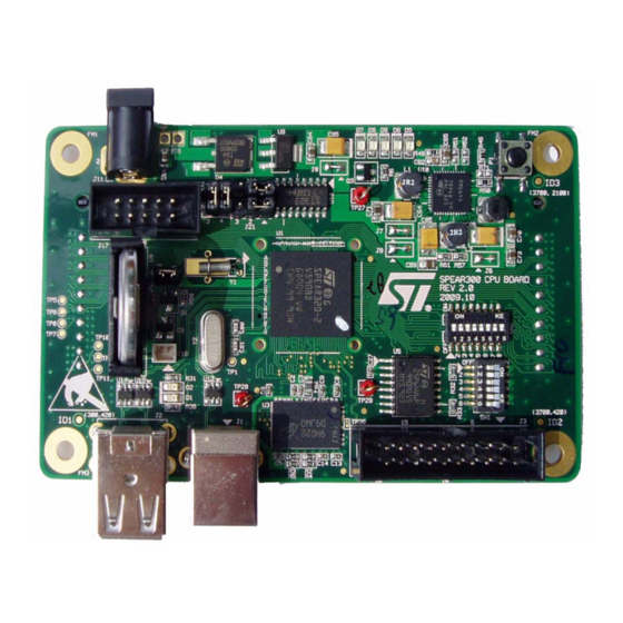
Page 3: Figure 1. Spear320 Cpu Evaluation Board
UM1015 User manual EVALSPEAr320CPU SPEAr320 CPU evaluation board Introduction This document applies to revision 2.0 SPEAr320 CPU evaluation boards. This board can be used to evaluate SPEAr320 microprocessors; the evaluation board kit comprises one board, one serial cable interface, and one power supply. -
Page 4: Table Of Contents
Contents UM1015 Contents Getting started ..........7 Connections . - Page 5 UM1015 List of tables List of tables Table 1. Switch SW1 bits [2:1] ............9 Table 2.
- Page 6 EVALSPEAr320CPU board block diagram........
-
Page 7: Getting Started
Getting started Getting started Warning: This board contains static sensitive devices. The EVALSPEAr320CPU board is shipped in protective anti-static packaging. Do not submit the board to high electrostatic potentials, and follow good practices for working with static sensitive devices. ●... -
Page 8: Block Diagram
Block diagram UM1015 Block diagram Figure 2. EVALSPEAr320CPU board block diagram 2.0.1 Dynamic memory subsystem The Dynamic memory subsystem comprises three major parts: Memory chip The SPEAr320 MPU supports up to 256 Mbytes of memory. Place and route is provided for 2 chips but only one has been populated. -
Page 9: Table 1. Switch Sw1 Bits [2:1]
UM1015 Block diagram 2.0.2 Static memory subsystem (Serial Flash memory) The SPEAr320 MPU supports up to 16 Mbytes of Serial Flash memory. Place and route for 2 blocks of 8 Mbytes are provided on the board, but only one is populated. It is based on an M25P64-VMF6P (Numonix) Serial Flash memory device. - Page 10 Block diagram UM1015 2.0.6 Real time clock (battery powered) The real time clock (RTC) is powered by an external battery (3V) in order to prevent data loss even if the main power supply is switched off. 2.0.7 General power supply From a 5 V external AC/DC regulator power source, this block generates all the required voltages as follows: ●...
-
Page 11: Expansion Connectors
UM1015 Expansion connectors Expansion connectors The CPU board has two 86-pin connectors (J12 and J13) that are used to extend the board. On the board the connectors are horizontally center-aligned, and the distance between the mechanical holes is 3400.00 th. Table 2 lists connector J12 pins. - Page 12 Expansion connectors UM1015 Table 2. CPU board extension connector J12 (continued) Description Description PL_GPIO11 PL_GPIO6 PL_GPIO19 PL_GPIO4 PL_GPIO15 PL_GPIO5 PL_GPIO14 PL_GPIO36 PL_GPIO41 PL_GPIO35 PL_GPIO31 +2.5V PL_GPIO32 +2.5V PL_GPIO25 +2.5V PL_GPIO22 +2.5V PL_GPIO21 INRESET PL_GPIO17 nRESET PL_GPIO12 +1.2V PL_GPIO10 +1.2V PL_GPIO7 +1.2V PL_GPIO1 +1.2V...
-
Page 13: Table 3. Cpu Board Extension Connector J13
UM1015 Expansion connectors Table 3. CPU board extension connector J13 Description Description PL_GPIO47 +3.3V PL_GPIO49 PL_GPIO63 PL_GPIO56 PL_GPIO46 PL_GPIO58 PL_GPIO57 PL_GPIO64 PL_GPIO61 PL_GPIO45 PL_GPIO66 PL_GPIO48 PL_GPIO69 PL_GPIO50 PL_GPIO72 PL_GPIO55 PL_GPIO73 PL_GPIO59 PL_GPIO70 PL_GPIO60 PL_GPIO67 PL_GPIO65 PL_GPIO71 PL_GPIO62 PL_GPIO75 PL_GPIO68 PL_GPIO82 PL_GPIO52 PL_GPIO76 PL_GPIO53... - Page 14 Expansion connectors UM1015 Table 3. CPU board extension connector J13 (continued) Description Description PL_CLK3 AIN7 PL_CLK2 PL_CLK1 ADC VREFP 1. Physically connected to the internal metal plane of the connector. Pins 77 through 81 and 82 through 86 are shorted together. 14/38 Doc ID 18124 Rev 1...
-
Page 15: Switch And Jumper Settings
1. Bits 3, 4, 5 and 6 enable you to set the Functional configuration. The default configuration is Configuration 3. For other configurations, refer to the SPEAr320 user manual available at www.st.com/spear. Doc ID 18124 Rev 1 15/38... -
Page 16: Switch 2 Settings
Switch and jumper settings UM1015 Switch 2 settings Table 7. Switch 2 settings Boot from SW2-1 SW2-2 SW2-3 SW2-4 SW2-5 SW2-6 SW2-7 SW2-8 USB_BOOT ETH (parameter from I2C ROM) ETH (parameter from SPI ROM) Serial NOR (default setting) Parallel NOR 8 (EMI with ACK) Parallel NOR 16 (EMI with ACK) Parallel NAND 8... -
Page 17: Jumpers And Connectors
UM1015 Switch and jumper settings Jumpers and connectors The jumpers and connectors numbered below refer to the CPU board schematics (available on www.st.com/spear). Sheet 4 ● Connector J3 is a standard 20-pin 2.54 mm connector used for JTAG connections. ●... -
Page 18: Board Components
Board components UM1015 Board components Table 8. CPU board components Component Designator Footprint Description C1 C2 C3 C4 C5 C6 C7 C8 C9 C10 C11 C12 C13 C14 C15 C16 C17 C18 C19 C20 C21 C22 C23 C24 C25 C26 C27 C28 C29 C30 C31 Capacitor... - Page 19 UM1015 Board components Table 8. CPU board components (continued) Component Designator Footprint Description R10 R11 R12 R13 R14 R15 R16 R17 Resistor R18 R19 0603 Resistor 0603 10k ohm 1% 0.1W R20 R21 R22 R23 R24 R25 C75 C76 Capacitor 0603 Ceramic capacitor 10 nF 10% 50V X7R 0603 C61 C62...
- Page 20 Board components UM1015 Table 8. CPU board components (continued) Component Designator Footprint Description Resistor R1 R53 0805 Resistor 0805 121k ohm 0.1% 0.1W R55 R56 Resistor 0603 Resistor 0603 150 Kohm 1% 0.1W Resistor R39 R40 0603 Resistor 0603 150 ohm 1% 0.1W Resistor 0603 Resistor 0603 330 ohm 1% 0.1W...
- Page 21 ST2052; STm Current limited power distribution switches switch RS-232 driver SO16 ST3232C; STm RS-232 driver and receiver and receiver ST LD1117S25TR; STm low drop fixed positive voltage Voltage regulator SOT223 regulator 2.5V 800mA STM811; STm Reset generator and power monitor 3.3V Reset circuit...
-
Page 22: Schematics
Schematics UM1015 Schematics Figure 5. Schematic interconnections 02 - DDR Interface 02 - DDR Interface.SchDoc VREF 03 - USB Interface 03 - USB Interface.SchDoc 04 - Misc 04 - Misc.SchDoc ADC_VREFP nRESET ADC_VREFP nRESET ADC_VREFN ADC_VREFN AIN[0..7] INRESET 05 - Power 05 - Power.SchDoc VREF VREF... -
Page 23: Figure 6. Ddr Interface Schematic
Figure 6. DDR interface schematic ADDR[0..13] DATA[0..15] DATA5 ADDR0 DATA4 ADDR0 DATA0 ADDR0 DATA0 ADDR0 DATA0 ADDR0 DATA4 ADDR1 DATA5 ADDR1 DATA0 ADDR0 DATA1 ADDR1 DATA1 ADDR1 DATA1 ADDR1 DATA0 ADDR2 DATA3 ADDR2 DATA1 ADDR1 DATA2 ADDR2 DATA2 ADDR2 DATA2 ADDR2 DATA3 ADDR3... -
Page 24: Figure 7. Usb Interface Schematic
Figure 7. USB interface schematic USB Interface 3.3V_SP 10 nF X7R 50V 10 nF X7R 50V BLM21BD601SN1D BLM21BD601SN1D 10 Kohm 10 Kohm USB_DEV_VBUS B_DEV_VDD3V3 BLM21BD601SN1D BLM21BD601SN1D USB_DEV_5V USB_DEV_VBUS USB_DEV_VDD3V3 USB_DEV_INF_DM B_HOST_VDD3V3 USB_HOST0_VDD3V3 2.5V_SP USB_DEV_DM 4.7 Kohm 4.7 Kohm USB_DEV_INF_DP USB_DEV_DM USB_HOST1_VDD3V3 USB_DEV_DP USB_DEV_DP... -
Page 25: Figure 8. Usb Power And Optional Part Schematic
150 Ohm 150 Ohm 150 Ohm Optional part USB_DEV_DM USB_DEV_INF_DM I/O1 I/O1 USB_DEV_DP USB_DEV_INF_DP I/O2 I/O2 USBLC6 USBLC6 USB_DEV_5V Vbus ST USBLC6-2SC6 ST USBLC6-2SC6 C102 C102 HOST0_DM HOST0_INF_DM I/O1 I/O1 HOST0_DP HOST0_INF_DP I/O2 I/O2 USBLC6 USBLC6 HOST0_5V Vbus ST USBLC6-2SC6... -
Page 26: Figure 9. Miscellaneous Interfaces Schematic
Figure 9. Miscellaneous interfaces schematic 3.3V 3.3V SMI_DATAOUT SMI_DATAIN 1 Kohm 1 Kohm SMI_CLK JTAG Connector SMI_nWE0 WR-VPP SMI_nCS0 1 Kohm 1 Kohm CSEL 3.3V 3.3V HOLD nTRST nTRST SMI_CLK SMI_CLK nTRST SMI_CLK SMI_DATAIN SMI_DATAIN SMI_DATAIN SMI_DATAOUT SMI_DATAOUT 3.3V SMI_DATAOUT M25P64 M25P64 SMI_nCS0... -
Page 27: Figure 10. Power Supply Schematic
LD1117S25TR LD1117S25TR 0 Ohm 0 Ohm DC POWER SOCKET 2.1MM DC POWER SOCKET 2.1MM MMSZ5232BT1 MMSZ5232BT1 ST LD1117S25TR ST LD1117S25TR 0 Ohm 0 Ohm 0.1 uF X5R 10V 0.1 uF X5R 10V 10 uF X5R 10V 10 uF X5R 10V PAD1 4.7 Kohm... -
Page 28: Figure 11. Customization Interface Schematic
Figure 11. Customization interface schematic PL_GPIO[0..97] PL_GPIO[0..97] PL_GPIO[0..97] PL_GPIO[0..97] 1.2V_SP 3.3V_SP PL_GPIO0 PL_GPIO97 3.3V 3.3V_SP 2.5V 2.5V_SP PL_GPIO0 PL_GPIO97 VDD1V2_1 VDD3V3_1 PL_GPIO1 PL_GPIO96 PL_GPIO1 PL_GPIO96 VDD1V2_2 VDD3V3_2 PL_GPIO2 PL_GPIO95 PL_GPIO2 PL_GPIO95 VDD1V2_3 VDD3V3_3 PL_GPIO3 PL_GPIO94 PL_GPIO3 PL_GPIO94 47 uF Tan 10V 47 uF Tan 10V 47 uF Tan 10V 47 uF Tan 10V... -
Page 29: Figure 12. Daughterboard Interface Schematic
Figure 12. Daughterboard interface schematic PL_GPIO[0..97] PL_GPIO[0..97] 1.8V GPIO2 PL_GPIO44 GPIO3 PL_GPIO39 RS232_TXD PL_GPIO40 RS232_RXD PL_GPIO38 PL_GPIO42 PL_GPIO29 PL_GPIO43 PL_GPIO37 PL_GPIO34 PL_GPIO30 PL_GPIO33 PL_GPIO28 PL_GPIO16 PL_GPIO26 PL_GPIO24 PL_GPIO27 PL_GPIO20 PL_GPIO9 PL_GPIO23 PL_GPIO13 PL_GPIO18 PL_GPIO8 3.3V PL_GPIO11 PL_GPIO6 PL_GPIO19 PL_GPIO4 PL_GPIO15 PL_GPIO5 0.1 uF X5R 10V 0.1 uF X5R 10V... -
Page 30: Figure 13. Schematic Revision History
Figure 13. Schematic revision history Revision History Revision History Revision Descriptions Date Revision Descriptions Date Initial release 20 May 2009 Change R49 Value to 56K ohm 23 Sep 2009 C78, C79 : connected to GND instead of 2.5V 28 May 2009 16 Oct 2009 Add signal nRESET to daughter-board connectors (pinout to be defined) Add TP30 for DQS1 test;... -
Page 31: Board Layout
UM1015 Board layout Board layout Figure 14. SPEAr320 CPU evaluation board layout (top view) Power (J11) Reset button (P1) Serial link (J17) JTAG (J3) USB device (J1) host (J2) JTAG (J3) Figure 15. SPEAr320 CPU evaluation board layout (bottom view) Doc ID 18124 Rev 1 31/38... -
Page 32: Revision History
UM1015 Revision history Hardware revision history Revision 2.0 SPEAr320 CPU evaluation boards are documented in revision 1 of the EVALSPEAr320CPU user manual. Earlier board revisions are documented in UM0842, the EVALSPEAr320PLC user manual. Document revision history Table 9. Document revision history... -
Page 33: A License Agreements
All other warranties, conditions or other terms implied by law are excluded to the fullest extent permitted by law. LIMITATION OF LIABILITIES. In no event ST or its licensors shall be liable to You or any third party for any indirect, special,... - Page 34 Demo Product if any. TERMINATION. ST may terminate this license at any time if You are in breach of any of its terms and conditions. Upon termination, You will immediately destroy or return all copies of the demo software and documentation to ST.
- Page 35 Licensed Software or any portion or derivative thereof, for use with processors manufactured by or for an entity other than ST is a material breach of this Agreement and requires a separate license from ST. No source code and/or object code relating to and/or based upon Licensed Software is to be made available by You to any third party for whatever reason.
- Page 36 You will take all reasonable precautions to ensure and monitor their compliance with such requirements. You agree to promptly notify ST in the event of a violation of any of the foregoing, and to cooperate with ST to take any remedial action appropriate to address the violation.
- Page 37 UM1015 License agreements SEVERABILITY If any provision of this agreement is or becomes, at any time or for any reason, unenforceable or invalid, no other provision of this agreement shall be affected thereby, and the remaining provisions of this agreement shall continue with the same force and effect as if such unenforceable or invalid provisions had not been inserted in this Agreement.
- Page 38 No license, express or implied, by estoppel or otherwise, to any intellectual property rights is granted under this document. If any part of this document refers to any third party products or services it shall not be deemed a license grant by ST for the use of such third party products or services, or any intellectual property contained therein or considered as a warranty covering the use in any manner whatsoever of such third party products or services or any intellectual property contained therein.
Need help?
Do you have a question about the EVALSPEAr320CPU and is the answer not in the manual?
Questions and answers