Table of Contents
Advertisement
Quick Links
AN5560
Application note
L9963 14 Cells BMC IC Evaluation Board Quick Guide
Introduction
This document is intended as quick guide to help the user in the startup phase of EVAL-L9963-MCU combining and
summarizing the information contained in EVAL-L9963-MCU and STSW-L9963 user manuals.
AN5560 - Rev 2 - November 2020
www.st.com
For further information contact your local STMicroelectronics sales office.
Advertisement
Table of Contents

Related Manuals for ST EVAL-L9963-MCU


Summary of Contents for ST EVAL-L9963-MCU
- Page 1 L9963 14 Cells BMC IC Evaluation Board Quick Guide Introduction This document is intended as quick guide to help the user in the startup phase of EVAL-L9963-MCU combining and summarizing the information contained in EVAL-L9963-MCU and STSW-L9963 user manuals. AN5560 - Rev 2 - November 2020 www.st.com...
-
Page 2: What You Need
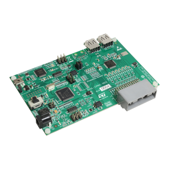
Note: Before using the UART/USB bridge FT2232H, the Virtual Com Port (VCP D2XX) driver needs to be installed. It can be downloaded by the FTDI Chip website. Figure 1. EVAL-L9963-MCU board Figure 2. EVAL-L9963-NDS board AN5560 - Rev 2 page 2/25... -
Page 3: Board Description
Main components and connectors Note: EVAL-L9963-MCU can be considered the only stage or the first stage of several stages. The port is the isolated vertical interface to the next stage (EVAL-L9963-NDS); A second L9963T (optional) may be needed to create a direct loop with the last stage (dual ring access);... -
Page 4: Block Diagram
AN5560 Block diagram Block diagram Figure 4. EVAL-L9963-MCU block diagram AN5560 - Rev 2 page 4/25... -
Page 5: Microcontroller Power Supply
AN5560 Microcontroller Power supply Microcontroller Power supply Figure 5. Microcontroller Power supply AN5560 - Rev 2 page 5/25... -
Page 6: L9963 External Connection And Power Supply
AN5560 L9963 external connection and power supply L9963 external connection and power supply Figure 6. L9963 external connection and power supply AN5560 - Rev 2 page 6/25... -
Page 7: Transceiver Settings
AN5560 Transceiver settings Transceiver settings Figure 7. Transceiver settings AN5560 - Rev 2 page 7/25... -
Page 8: Possible Connection For Battery Simulation
AN5560 Possible connection for battery simulation Possible connection for battery simulation Figure 8. Battery simulation 1 Figure 9. Battery simulation 2 AN5560 - Rev 2 page 8/25... -
Page 9: Preliminary Action To Open The Gui
AN5560 Preliminary action to open the GUI Preliminary action to open the GUI Install the following SW on your PC: • NI Labview-runtime 2014 • NI VISA-RUNTIME • FTDI driver – Before using the UART/USB bridge FT2232H, the Virtual Com Port (VCP) driver needs to be installed. It can be downloaded by the FTDI Chip website. -
Page 10: Usb To Pc Connection
AN5560 USB to PC connection USB to PC connection Figure 10. USB to PC connection AN5560 - Rev 2 page 10/25... -
Page 11: Device Manager Appearance
AN5560 Device Manager appearance Device Manager appearance If FTDI Virtual COM PORT (VCP D2XX) driver has been correctly installed, you will find in Windows Device manager a USB serial port under Ports (COM&LPT). Take note of the COM port number (i.e. COM13). Figure 11. -
Page 12: Gui Usage And Setup
AN5560 GUI usage and setup GUI usage and setup 11.1 Connection Steps: Select COM port according to your device manager. The COM led will become green; Press on “get firmware version” button to check the communication with uC and the firmware version. The version should be 1.5;... -
Page 13: Threshold Configuration
AN5560 Threshold configuration 11.2 Threshold configuration Steps: Select Cell overvoltage and undervoltage. i.e. UV 2.8 V and OV 4.250 V; The VCELL_THRESH_UV_OV register will be automatically updated; Select Dev ID 1; Select Write; Press on “Single write/read” button; If communication with L9963 is ok the ACK LED will become green. Figure 13. -
Page 14: Figure 14. Threshold Configuration 2
AN5560 Threshold configuration Steps: Select Battery overvoltage and undervoltage. i.e. UV 39.2 V and OV 59.5 V; The VBAT_SUM_TH register will be automatically updated; Select Dev ID 1; Select Write; Press on “Single write/read” button; If communication with L9963 is ok the ACK LED will become green. Figure 14. -
Page 15: Measure Enabling
AN5560 Measure enabling 11.3 Measure enabling Steps: Select cell voltage gauge with the EN check box. At least Cells 1, 2, 13, 14 must be selected; The VCELLS_EN register will be automatically updated; Select Dev ID 1; Select Write; Press on “Single write/read” button; If communication with L9963 it’s ok the ACK LED will become green. -
Page 16: Measure Starting
AN5560 Measure starting 11.4 Measure starting Steps: Select time interval. i.e. 100 ms. This is the refresh rate of GUI measurement; Press on “Time interval” button to apply setting. ACK LED will become green; Check Diagnostic checkbox to start measurement. Figure 16. -
Page 17: Alternative Measure Setting
AN5560 Alternative measure setting 11.5 Alternative measure setting Figure 17. Alternative measure setting AN5560 - Rev 2 page 17/25... -
Page 18: Measurements Example
AN5560 Measurements example 11.6 Measurements example Figure 18. Setup Figure 19. Results AN5560 - Rev 2 page 18/25... -
Page 19: Diagnostic
AN5560 Diagnostic 11.7 Diagnostic All the diagnostics are available in the Diagnostic-Information tab. They are updated at the same rate as measurement. Figure 20. Diagnostic AN5560 - Rev 2 page 19/25... -
Page 20: Appendix A Reference Documents
AN5560 Reference documents Appendix A Reference documents Table 1. Reference documents Doc Name Title UM2698 034111 EVAL-L9963-MCU Evaluation Board UM2734 034356 L9963 evaluation graphical user interface AN5560 - Rev 2 page 20/25... -
Page 21: Revision History
AN5560 Revision history Table 2. Document revision history Date Version Changes 15-Sep-2020 Initial release. 17-Nov-2020 Updated Title in cover page. AN5560 - Rev 2 page 21/25... -
Page 22: Table Of Contents
AN5560 Contents Contents What you need ..............2 Board description . - Page 23 AN5560 List of tables List of tables Table 1. Reference documents ............. . . 20 Table 2.
- Page 24 EVAL-L9963-MCU block diagram ........
- Page 25 ST’s terms and conditions of sale in place at the time of order acknowledgement. Purchasers are solely responsible for the choice, selection, and use of ST products and ST assumes no liability for application assistance or the design of Purchasers’...
Need help?
Do you have a question about the EVAL-L9963-MCU and is the answer not in the manual?
Questions and answers