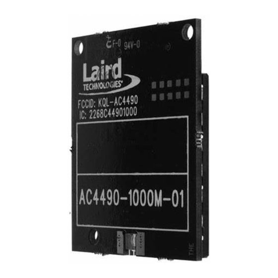
Summary of Contents for Laird RAMP-AC RF
- Page 1 RAMP-AC RF DVK Hardware ’ UIDE ERSION Americas: +1-800-492-2320 Option 2 Europe: +44-1628-858-940 Hong Kong: +852-2923-0610 wireless.support@lairdtech.com www.lairdtech.com/ramp Arrow.com. Downloaded from...
- Page 2 Ramp-AC RF DVK Hardware Version 1.0 EVISION ISTORY Version Date Changes 30 April 2014 Initial Release CONN-GUIDE-RAMP-AC-DVK-HW Americas: +1-800-492-2320 Option 2 Europe: +44-1628-858-940 Hong Kong: +852-2923-0610 wireless.support@lairdtech.com www.lairdtech.com/ramp Arrow.com. Arrow.com. Downloaded from Downloaded from...
-
Page 3: Table Of Contents
Ramp-AC RF DVK Hardware Version 1.0 ONTENTS Contents ..............................3 Introduction ............................... 4 Hardware ..............................4 AC Series DVK Board ..........................4 Interfacing the AC DVK to RS232 Hardware ..................9 Interfacing the AC DVK to RS485 Hardware ..................9 Power Requirements .......................... -
Page 4: Introduction
Version 1.0 NTRODUCTION The Laird RF RAMP-AC Development Kit board is the standard interface for software development on all Laird RAMP-AC products. This board is connected to a Windows PC via RS-232 connector and programmed via the Laird Configuration Utility. This guide covers the hardware specifications of the development board,... - Page 5 Ramp-AC RF DVK Hardware Version 1.0 Table 1: Switch and Jumper Settings Switch / Jumper Description When this switch is moved to the Program Mode position, the RTS pin from the DB9/USB connector is connected to the Command/Data pin (AC4490, AC4486, AC4424, AC4790, AC4868), the TE pin (AC3124, AC1524) and the Pktmode pin (AC5124) of the transceiver.
- Page 6 Ramp-AC RF DVK Hardware Version 1.0 Switch / Jumper Description RADIO VOLTAGE If this jumper is moved to the +5V Radio position, the transceiver is powered with 5V. (J9) If this jumper is moved to the +3.3V Radio position, the transceiver is powered with 3.3V.
- Page 7 Ramp-AC RF DVK Hardware Version 1.0 Description With a client transceiver, it lights if the client transceiver is in range of a server transceiver IN RANGE with the same system ID and channel number. With a server transceiver, it always lights when the server is powered in normal mode and is ready to accept data.
- Page 8 Ramp-AC RF DVK Hardware Version 1.0 AC1524 AC3124 AC4490 AC4868 AC5124 AC4424 AC1524 AC4790 Type AC5124 AC4424 AC4486 J1 Pin Signal Signal AC4490 AC3124 Signal Pin # Signal Name Signal Name Name AC4486 Signal Name Name Name AC4868 Pin #...
-
Page 9: Interfacing The Ac Dvk To Rs232 Hardware
Ramp-AC RF DVK Hardware Version 1.0 AC1524 AC3124 AC4490 AC4868 AC5124 AC4424 AC1524 AC4790 Type AC5124 AC4424 AC4486 J1 Pin Signal Signal AC4490 AC3124 Signal Pin # Signal Name Signal Name Name AC4486 Signal Name Name Name AC4868 Pin # I –... -
Page 10: Power Requirements
Ramp-AC RF DVK Hardware Version 1.0 RS-485 Pin Name Description This is regulated 5V output from the serial board for general purpose use. A maximum of 100 mA should be drawn through this node. Power Requirements The serial board employs a National LM2940 linear regulator to regulate the incoming voltage to 5VDC. Due to heat dissipation limitations and current requirements, a maximum of 10VDC should be present at connector J4.


Need help?
Do you have a question about the RAMP-AC RF and is the answer not in the manual?
Questions and answers