
Related Manuals for Laird DVK-WLM400


Summary of Contents for Laird DVK-WLM400
- Page 1 WISM+ DVK MANUAL Version 1.00 Page i DVK-WLM400/402 Developer Kit Manual © Laird Technology 2010...
- Page 2 God, accidents, electrical irregularity, or other causes beyond Laird Technologies’ control, or claim by other than the original purchaser. In no event shall Laird Technologies be responsible or liable for any damages arising: From the use of product; From the loss of use, revenue or profit of the product;...
- Page 3 This is the PC based executable program for configuring and running performance tests for the WISM+/Dev Kit. WIF.EXE IS ACCESSABLE AFTER THE INSTALLATION BY… StartAll ProgramsWism+Wism+ Config Tool WISM+ This refers to a WLM400 (for US) or WLM402 (for CE) © Laird Technology 2010...
-
Page 4: Table Of Contents
............................. 18 PERATION WIF A ..........................18 CCESS OINT WISM+ A ....................19 ONFIGURING CCESS OINT ABLE WISM+ A ........................19 ONFIGURE NTENNA PERFORM A WIRELESS PING PCWISM+ ....................20 AT MODE WIRELESS PING WISM+PC ....................24 © Laird Technology 2010... - Page 5 USING WISM+ IN BRIDGE MODE W/ACCESS POINT ................29 REGULATORY CONSIDERATIONS ......................32 10.1 ............................32 ANADA 10.2 ................................32 UROPE DEV KIT DESIGN ............................33 11.1 PCB S ............................. 33 TACK 11.2 PCB L ..........................34 AYOUT RAWING 11.3 ..............................35 CHEMATICS © Laird Technology 2010...
-
Page 6: Overview
(Dev Kit) which allows you to connect a PC to the WISM+ using your choice of interface. A configuration/performance tool (WIF.exe) is provided so you can set up custom WISM+ configurations, then and measure the performance of the WISM+ wireless module from Laird Technologies. The download and installation of this package provides you with the following executables by clicking…... -
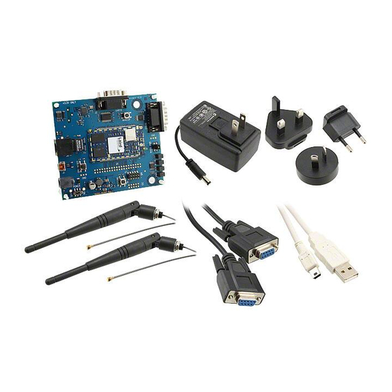
Page 7: Parts List
USB cable “type A to mini” for WISM+ Dev Kit connection to connect to a PC • RS-232 serial cable (female-female) for WISM+ COM port connection to a PC serial port Note: an Ethernet cable is not provided. © Laird Technology 2010... -
Page 8: Hardware
40 pin Hole Switching Restore Header Power Defaults Supply Button Header Dev Kit Design Full schematics and assembly drawing are provided (see section: “ ”). Blocks in this colour are essential things to become familiar with. © Laird Technology 2010... -
Page 9: Host Interfaces
(creating a positive RS-232 level voltage to the PC). If WISM+ cannot accept serial input, it drives the pin high (creating a negative RS-232 voltage). DB9_RI This pin should be ignored at the host. © Laird Technology 2010... -
Page 10: Spi Header
This is the SPI Slave Select input to the WISM+. SPI_SS SPI_SS This is driven low by a SPI Master device to frame the data transfer. Ground pin connected to the ground plane of the Dev Kit PCB. © Laird Technology 2010... -
Page 11: I2C Header
2.2.6 Debug Com Port This is an RS-232 DCE serial port. This port outputs internal debug information which can be used by Laird Technologies to attempt to debug WISM+ operations. There is no hardware flow control. DB9 Pin 2 is transmit data to the PC, and DB9 pin 3 is receive data from the PC. -
Page 12: Power/Gnd
WISM+ “ ” pin (WISM+ pin#59) CONNECTED 2.5.4 SPI This LED will be lit whenever the SPI port is being used as the host interface, and communications are active over the SPI port. © Laird Technology 2010... -
Page 13: Buttons
RESET_IN 2.6.2 Restore Defaults Button The Restore Defaults Button will restore the WISM+ with the saved environment which was set up at Laird production/test time. The WISM+ must perform a boot while the Restore Defaults Button is pressed and remain pressed until the heartbeat LED begins flashing in order for this function to work. -
Page 14: Using At Commands With Pc Serial Port
Click “OK” and you will see the following screen… Select the COM port connected your to the WISM+ and you will you will see this Click “OK” and the following COM port properties screen will appear… © Laird Technology 2010... - Page 15 “ENTER” key while typing in HyperTerminal, that a Line End character is sent with the string to the WISM+. Click the “OK” button and your COM port configuration is complete. © Laird Technology 2010...
- Page 16 NO hardware flow control • You are not using the supplied serial cable between the Dev Kit and the PC serial port • You may not have selected “Send line ends with line feed” in the HyperTerminal ASCII setup © Laird Technology 2010...
- Page 17 By typing “at+help” and “ENTER” at the WISM+ prompt, you will see a list of all of the AT commands which can be exercised. Refer to the “AT Command Reference” for descriptions of the AT commands. © Laird Technology 2010...
-
Page 18: Software- Wif
WIF.exe has been installed by running the setup file from the download and is launched by clicking… StartAll ProgramsWism+Wism+ Config Tool WIF.exe actually exists in the following folder… c:\Program Files\Laird Technologies\Wism+ The WIF.exe tool is used for the following: •... -
Page 19: Configuring Pc Serial Port For Wif.exe
Issue an “at+quit” AT command using HyperTerminal (and there will be no response). • Now quit the HyperTerminal session (or hang up the hook) which will release the serial port for WIF.exe. • Starting WIF.exe over the PC Serial port Now go to section: “ ” © Laird Technology 2010... -
Page 20: Configuring Pc Ethernet Port For Wif.exe
Stopping services which interfere with network traffic At Laird, we use Symantec virus protection and network traffic monitoring. Part of its job is to look for potentially harmful network traffic which might be hacking into your computer. The WIF to WISM+ communications look potentially harmful to these types of services, and the services will interfere and capture the network traffic thus keeping WIF.exe from communicating with WISM+ over the Ethernet interface. -
Page 21: Starting Wif.exe
After setting up the COM port parameters click “OK”. If everything is working properly, you will see the WIF front screen populated with the current state saved in WISM+ constant memory. WIF.exe Operation Now go to section: “ ”. © Laird Technology 2010... -
Page 22: Starting Wif.exe Over Pc Ethernet Port
PC’s wired network connection, Click OK. If everything is working properly, you will see the WIF front screen populated with the current state saved in WISM+ constant memory. WIF.exe Operation Now go to section: “ ”. © Laird Technology 2010... -
Page 23: Wif.exe Operation
You will see… • All access points and Ad-Hoc connections • Their SSID’s • Their channel • Associated Signal level (RSSI) • What type of security © Laird Technology 2010... -
Page 24: Configuring Wism+ Access Point Table
It constantly evaluates signal to noise ratio and packet error rates and will make decisions to switch antennae. By default, antenna #1 is configured to be used for transmit and receive. © Laird Technology 2010... -
Page 25: Perform A Wireless Ping PcWism
SSID of “Range Test” with a “Static” IP address of 192.168.1.22 & subnet mask 255.255.255.0. Now click “OK” and then close WIF. Now, reset the WISM+ in order for the changes to be in effect. © Laird Technology 2010... - Page 26 Right Click on the Wireless Network Connection and select “Properties”. The screen below will appear… First, pull the bar down to get to the end of the list Next, Select “Internet Protocol (TCP/IP)” Now click “Properties” © Laird Technology 2010...
- Page 27 WISM+ in Ad-Hoc mode) and must be in range of the Press Connect, and you will get the following warning… Click “Connect Anyway” and you are now connected to the WISM+ Ad-Hoc connection as shown below… © Laird Technology 2010...
- Page 28 Four pings will be performed by default. You can also type “ping –help” and see all of the options allowed with the ping command. You can set the number of pings to a large number and then perform range testing. © Laird Technology 2010...
-
Page 29: At Mode Wireless Ping Wism+Pc
AT ping command WISM+ Ping responses from pinging the remote computer NOTE: In the ping command (shown above), the target of the ‘PING’ is the IP address of the remote PC configured in Ad-Hoc mode. © Laird Technology 2010... -
Page 30: Using The Performance Tool In Ad-Hoc Mode
It displays the total number of 1500 byte packets received. You can scale the units of the meters in kb/s or Mb/s. You can also reset the peak rate meter and the packet count by pressing the “Reset” button © Laird Technology 2010... - Page 31 WinPcap package. SPI works as well, but in all cases, the throughput is held back due to how fast the packets can actually be given to the WISM+. © Laird Technology 2010...
-
Page 32: Using The Performance Tool In Infrastructure Mode
PC might not be connected directly to the Access Point or Router, but over a network. The PCs could have Static IP addresses, etc. Using the Performance Tool in Ad-Hoc Mode Refer to section: “ ” for a description of using WIF.exe to transmit packets on the WISM+ Host PC and dboard.exe operation on the Remote PC. © Laird Technology 2010... - Page 33 Select “Infrastructure” Once Bridged is un- selected and Infrastructure is selected, press the configure button, and set the first access point table entry to match the SSID of the access point with DHCP as shown below... © Laird Technology 2010...
-
Page 34: Using Wism+ In Bridge Mode W/Access Point
Make sure that both laptops have their TPC properties (for the wired Ethernet connection) set up to obtain an IP address automatically (DHCP). • Configure the access point to have an SSID (in this example “TEST”) and no security. © Laird Technology 2010... - Page 35 Now, press “Ok”, and then exit WIF.exe, and then re-boot the WISM+ by pressing RESET, or cycling power. Now connect the WISM+ Dev Kit to the WISM+ HOST PC via an Ethernet cable. When WISM+ connects to the Access point (joins the wireless network) its “WLAN LED” will be lit. © Laird Technology 2010...
- Page 36 Now compute the throughput of the system by multiplying the size of the file (in bytes) times 8 (bits per byte) and then dividing by the transfer time in seconds. • This test uses 802.11g/b and TCP stack on the PCs, performing network level retries and guaranteeing the file delivery. © Laird Technology 2010...
-
Page 37: Regulatory Considerations
The WLM402 (on the Dev Kit board) has been tested and found to comply with the following CE standards… • ETSI EN 301 489-1 V1.8.1 (2008-04) • ETSI EN 301 489-17 V1.2.1 (2002-08) • ETSI EN 300 328-2 V1.7.1 (2006-05) The test reports are available upon request. © Laird Technology 2010... -
Page 38: Dev Kit Design
The Ethernet PHI interface requires good PCB design practices in order to yield acceptable EMI suppression. Use of ground plane which encloses noisy signals and clocks is imperative in order to produce a quiet design. Bill of Materials and Gerber Files are available upon request. © Laird Technology 2010... -
Page 39: Pcb Layout Drawing
WISM+ DVK MANUAL Version 1.00 Page 34 11.2 PCB Layout Drawing The following is an assembly drawing of the Dev Kit PCB indicating reference designators and parts placements. The corresponding schematics are shown in the following section. © Laird Technology 2010... -
Page 40: Schematics
WISM+ DVK MANUAL Version 1.00 Page 35 11.3 Schematics © Laird Technology 2010... - Page 41 WISM+ DVK MANUAL Version 1.00 Page 36 © Laird Technology 2010...
- Page 42 WISM+ DVK MANUAL Version 1.00 Page 37 © Laird Technology 2010...
- Page 43 WISM+ DVK MANUAL Version 1.00 Page 38 © Laird Technology 2010...
Need help?
Do you have a question about the DVK-WLM400 and is the answer not in the manual?
Questions and answers