
Related Manuals for Laird DVK-BL600-SA


Summary of Contents for Laird DVK-BL600-SA
- Page 1 Bluetooth Low Energy (BLE) Development Kit User Manual Version 2.0 DVK-BL600-SA, DVK-BL600-SC, DVK-BL600-ST Americas: +1-800-492-2320 Option 2 Europe: +44-1628-858-940 Hong Kong: +852-2923-0610 www.lairdtech.com/bluetooth...
-
Page 2: Revision History
BL600 Development Kit Version 2.0 EVISION ISTORY Revision Date Changes Version 1.0 22/02/2013 First Public Release 0 rev 1 PCB Version 2.0 11/04/2013 Technical and grammatical revisions for rev 02 PCB CONN-GUIDE_BL600_DVK_v2_0 Americas: +1-800-492-2320 Option 2 Europe: +44-1628-858-940 Hong Kong: +852-2923-0610 www.lairdtech.com/bluetooth... -
Page 3: Table Of Contents
Version 2.0 ONTENTS Revision History ............................2 Contents ..............................3 Laird Bluetooth Low Energy Development Kit ....................4 1. Overview ..............................4 1.1 Introduction ............................4 1.2 Package Contents ..........................4 2. BLE Development Kit – Main Development Board ..................5 2.1 Key Features ............................. -
Page 4: Laird Bluetooth Low Energy Development Kit
BASIC runtime engine FW version v1.1.50.0 or greater. Introduction The Laird BLE development kit is designed to support the rapid development of applications and software for the smart BL600 series of BLE modules featuring Laird’s innovative event driven programming language –... -
Page 5: Ble Development Kit - Main Development Board
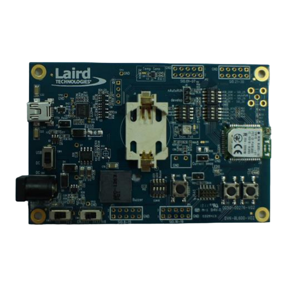
AT command mode by default. smart s smart BASIC applications are simple and easy to develop for any BLE application. Sample BASIC applications are available to download from the Laird BL600 product webpage or via the Laird global FAE network. - Page 6 BL600 Development Kit Version 2.0 Understanding the Development Board DIP switch CON13 SIO_21-30 SMA Connector Coin-cell SIO_00-07 JP5 UART for BL600-ST Variant DIP switch CON14 Interface battery holder FTDI-FT232R USB CON4 DC/USB Power BL600-Sx Source module Switch LED1 LED0 Button DC Jack Input CN1 JTAG JP1...
-
Page 7: Functional Blocks
BL600 Development Kit Version 2.0 3. F UNCTIONAL LOCKS The development board is formed from the following major functional blocks: Power Supply Figure 2: BL600 power supply The development board can be powered from 4.5-5.5 V supply (into DC jack connector CN1), 3xAAA batteries (holder J7 mounted on underside of board), or from the USB (type mini-B connector (CON4). -
Page 8: Reset Button
BL600 Development Kit Version 2.0 On the development board, the power domain: VCC_nRF supplies the BL600 series module only. Current measuring block on development board only measures the current into power domain VCC_nRF. VCC_IO_UART supplies the FTDI chip IO and all other sensors and circuitry. ... - Page 9 BL600 Development Kit Version 2.0 3.4.2 UART Interface Driven by USB USB Connector. The development kit provides a USB Type mini-B connector (CON4) which allows connection to any USB host device. The connector optionally supplies power to the development kit and the USB signals are connected to a USB to serial convertor device (FT232R), when SW4 is set to ‘USB’...
-
Page 10: Nautorun Pin And Operating Modes
BL600 Development Kit Version 2.0 nAutoRUN Pin and Operating Modes On the development board USB_DTR output (FTDI chip U9) from PC is wired to BL600 module pin SIO.28 (pin40) which is the nAutoRUN pin. Note: smart BASIC runtime engine FW checks for the status of nAutoRUN during power-up or reset. The nAutoRUN pin detects if the BL600 module should power up into “Interactive / Development Mode (3.3 V)”... -
Page 11: Software
UW Terminal is a terminal emulation application capable of running on Windows 98, ME, 2000, XP, Windows 7, and Windows 8 operating systems. It was developed specifically to aid development and testing of Laird modules. It allows connection to serial devices using any combination of the communications parameters listed in Table 4-1. -
Page 12: Breakout Connector Pinouts
BL600 Development Kit Version 2.0 5. B REAKOUT ONNECTOR INOUTS JP2, JP3, JP4, JP5 SIO (Special Input / Output Sockets) Breakout Connectors Access to all 28 BL600 series module signal pins (SIO’s = signal Input /Output) is available on four connectors JP2, JP3, JP4, JP5 (2.54 mm pitch 2x5 headers). - Page 13 DIO: Digital Input or Output AIN: Analog Input smart BASIC runtime engine FW Default Direction In BL600 module Note: SIO_20 is a No Connect (N/C) and is reserved by Laird for future use. CONN-GUIDE_BL600_DVK_v2_0 Americas: +1-800-492-2320 Option 2 Europe: +44-1628-858-940 Hong Kong: +852-2923-0610...
-
Page 14: Additional Peripherals / Sensors
BL600 Development Kit Version 2.0 5.1.4 JP5 SIO_21-30 Default Alternate Default Comment Designation Function Function Direction SIO_21 UART_TX Output SIO_22 UART_RX Input SIO_23 UART_RTS Output SIO_24 UART_CTS Input SIO_25 Input UART_DTR (CON12) on DVK SIO_26 DO NOT CONNECT SIO_27 DO NOT CONNECT SIO_28 nAutoRUN Input ONLY... - Page 15 0 followed by a 1 to SIO_15 repeatedly in a loop. smart smart Sample BASIC applications are available from a Laird FAE, or refer to “bzt.buzzer.test.sb” in the BASIC sample application library on BL600 product pages at: http://lairdtech.com/Products/Embedded-Wireless-Solutions/Bluetooth-Radio-Modules/BL600-Series/ 5.2.2 Temperature Sensor...
- Page 16 BL600 Development Kit Version 2.0 Key specifications of the LM20BIM7: Output type Analogue output Accuracy at 30ºC ±1.5ºC ±4ºC (max) Accuracy at 40ºC to +85ºC approx. ±2.5ºC ±5ºC (max) Power supply voltage range +2.4 V to 5.5 V Current Drain 10 uA (max) Output impedance 160 Ohms (max)
- Page 17 BL600 Development Kit Version 2.0 The Trim Potentiometer (R9) can be disconnected from BL600 series module by micro-DIP switch CON14. Physical micro-DIP switch body has text “ON” on the closed side. The Trim Potentiometer (R9) can be disconnected from supply rail by cutting the solder bridge SB2. tpt.trimpot.test.sb The Trim Potentiometer generates a voltage range of 0 V to ~0.9 V at C3 (CON14 pin3), see file smart...
-
Page 18: Other Features
BL600 Development Kit Version 2.0 If SIO_18 and SIO_19 are needed elsewhere, the LEDs can be disconnected by micro-DIP switch CON15. Physical micro-DIP switch body has text “ON” on the closed side. The buttons have no external pull-up resistor, so to use the buttons the SIO_16 and SIO_17 pins must be configured smart as an input with internal pull-up resistor. -
Page 19: Additional Documentation
IC U8. 7. A DDITIONAL OCUMENTATION Laird offers a variety of documentation and ancillary information to support our customers through the initial evaluation process and ultimately into mass production. Additional documentation includes: smart BL600 – BASIC User manual ... -
Page 20: Appendix
BL600 Development Kit Version 2.0 8. A PPENDIX 8.1 Coin Cell Insertion To insert the coin cell, follow these steps: Push the coin cell against positive contact spring of holder J8. NOTE: The coin cell sits below the positive contact spring (as shown with arrow). Figure 12: Inserting the coin cell (step 1) Push the coin cell down into the holder (J8). -
Page 21: 8.2 Coin Cell Removal
Copyright © 2013 Laird Technologies, Inc. All rights reserved. The information contained in this manual and the accompanying software programs are copyrighted and all rights are reserved by Laird Technologies, Inc. Laird Technologies, Inc. reserves the right to make periodic modifications of this product without obligation to notify any person or entity of such revision.
Need help?
Do you have a question about the DVK-BL600-SA and is the answer not in the manual?
Questions and answers