Advertisement
Quick Links
Advertisement

Related Manuals for Laird Sterling-EWB


Summary of Contents for Laird Sterling-EWB
- Page 1 Version 1.1...
- Page 2 Initial version Dave Neperud Jay White Fixed typo in EWB development Kit power 06 Aug 2019 Dave Neperud Jay White supply diagram (Figure 4) https://www.lairdconnect.com/ Americas: +1-800-492-2320 © Copyright 2019 Laird. All Rights Reserved Europe: +44-1628-858-940 Hong Kong: +852 2923 0610...
- Page 3 Overview ..................................... 4 Laird Sterling-EWB Development Kit Part Numbers ......................4 Package Contents ................................4 Development Kit – Main Development Board ........................4 Key Features ................................4 Understanding the Development Board ..........................5 EWB-DVK Default Configuration and Jumper Settings ....................6 Functional Blocks ................................
- Page 4 The Laird Sterling-EWB development kit provides a platform for development of embedded Wi-Fi and/or Bluetooth Low Energy (BLE) applications. This document describes the development board hardware, highlighting the setup and interfaces available to maximize user flexibility in developing these applications.
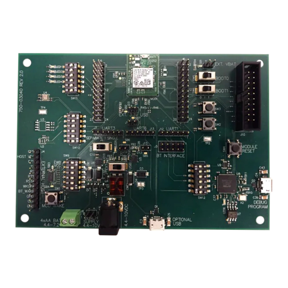
- Page 5 J15 3.3V DVK Select USB or switch Header Current Ext DC power 4.4-10V DC source Measure Figure 1: Development board contents and locations https://www.lairdconnect.com/ Americas: +1-800-492-2320 © Copyright 2019 Laird. All Rights Reserved Europe: +44-1628-858-940 Hong Kong: +852 2923 0610...
- Page 6 The default power connection is using the provided USB cable plugged into the DEBUG/PROGRAM micro- USB port. Figure 3: Correct EWB development board 455-00030 or 455-00031 switch settings (image for 455-00030) https://www.lairdconnect.com/ Americas: +1-800-492-2320 © Copyright 2019 Laird. All Rights Reserved Europe: +44-1628-858-940 Hong Kong: +852 2923 0610...
- Page 7 The EWB module currently does not support the external USB interface, so the VDD_USB pin is tied directly to 3V3_MCU. The VDD_USB pin supplies power to GPIO PA11 and PA12 on the EWB module. https://www.lairdconnect.com/ Americas: +1-800-492-2320 © Copyright 2019 Laird. All Rights Reserved Europe: +44-1628-858-940 Hong Kong: +852 2923 0610...
- Page 8 USB port to interface with the Cypress WICED® software development kit as well as provide a COM port for monitoring the debug output of the Laird Sterling-EWB demo application. The EWB development board boot option is configured by setting SW5 and SW6...
- Page 9 Note: The EWB MCU connection to the buttons can be removed by switching positions 3(SW3) and 6(SW2) of SW10 to the OFF position. https://www.lairdconnect.com/ Americas: +1-800-492-2320 © Copyright 2019 Laird. All Rights Reserved Europe: +44-1628-858-940 Hong Kong: +852 2923 0610...
- Page 10 To allow this capability, the shorted solder bridge SB4 needs to be cut on the development board (Figure https://www.lairdconnect.com/ Americas: +1-800-492-2320 © Copyright 2019 Laird. All Rights Reserved Europe: +44-1628-858-940 Hong Kong: +852 2923 0610...
- Page 11 Figure 7: External HOST interface schematic and location of solder bridge modifications https://www.lairdconnect.com/ Americas: +1-800-492-2320 © Copyright 2019 Laird. All Rights Reserved Europe: +44-1628-858-940 Hong Kong: +852 2923 0610...
- Page 12 Three Bluetooth General Purpose I/O lines are available for expansion capability. BT_HOST_WAKE output signal pin indicates when the EWB module Bluetooth radio requires attention. https://www.lairdconnect.com/ Americas: +1-800-492-2320 © Copyright 2019 Laird. All Rights Reserved Europe: +44-1628-858-940 Hong Kong: +852 2923 0610...
- Page 13 Table 6: J5 and J6 pin mapping Connection Connection Connection Connection MICRO_WKUP/PA0 PC11 MICRO_RST_N SPI4_NSS/PE11 PC13 SPI4_SCK/PE12 SPI4_MISO/PE13 I2C2_SCL/PB10 SPI4_MOSI/PE14 I2C2_SDA/PB11 PD10 PE15 PB12 PB15 https://www.lairdconnect.com/ Americas: +1-800-492-2320 © Copyright 2019 Laird. All Rights Reserved Europe: +44-1628-858-940 Hong Kong: +852 2923 0610...
- Page 14 (Figure 11). Figure 11: Current measurement schematic and PCB modifications https://www.lairdconnect.com/ Americas: +1-800-492-2320 © Copyright 2019 Laird. All Rights Reserved Europe: +44-1628-858-940 Hong Kong: +852 2923 0610...
- Page 15 PE15 MICRO_SPI2_NSS PB12 MICRO_SPI2_SCK PB13 MICRO_SPI2_MISO PB14 MICRO_SPI2_MOSI PB15 MICRO_GPIO27 MICRO_GPIO25 PD10 QUADSPI_BK1_NCS MICRO_I2S2_CK MICRO_I2S2_MCK MICRO_USART1_RX PA10 MICRO_USART1_TX MICRO_GPIO_26 MICRO_GPIO_28 MICRO_I2C1_SDA MICRO_USART1_CTS PA11 https://www.lairdconnect.com/ Americas: +1-800-492-2320 © Copyright 2019 Laird. All Rights Reserved Europe: +44-1628-858-940 Hong Kong: +852 2923 0610...
- Page 16 MICRO_I2S_DI OSC_32K_OUT PC15 MICRO_WKUP QUADSPI_BK1_IO2 MICRO_I2S2_SD SPI1 is used for the internal EWB module 16 Mb flash communication (PA4, PA5, PA6, and PA7). https://www.lairdconnect.com/ Americas: +1-800-492-2320 © Copyright 2019 Laird. All Rights Reserved Europe: +44-1628-858-940 Hong Kong: +852 2923 0610...
- Page 17 MISO PA13 PA14 PA15/ BOOT1 BK1_NCS MOSI PB10 PB11 CKIN PB12 PB13 PB14 MISO PB15 MOSI MOSI BK2_IO2 BK2_IO3 PC11 MISO BK2_NCS PC13 https://www.lairdconnect.com/ Americas: +1-800-492-2320 © Copyright 2019 Laird. All Rights Reserved Europe: +44-1628-858-940 Hong Kong: +852 2923 0610...
- Page 18 Laird materials or products for any specific or general uses. Laird, Laird Technologies, Inc., or any of its affiliates or agents shall not be liable for incidental or consequential damages of any kind. All Laird products are sold pursuant to the Laird Terms and Conditions of Sale in effect from time to time, a copy of which will be furnished upon request.
Need help?
Do you have a question about the Sterling-EWB and is the answer not in the manual?
Questions and answers