Advertisement
Quick Links
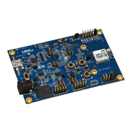
DVK-BT900-Sx Development Kit
Hardware Integration Guide
Version 1.0
DVK-BT900-SA, DVK-BT900-SC
Laird Technologies
Americas: +1-800-492-2320
Europe: +44-1628-858-940
Hong Kong: +852 2923 0610
Embedded Wireless Solutions Support Center: http://ews-support.lairdtech.com
www.lairdtech.com/bluetooth
Advertisement

Related Manuals for Laird DVK-BT900-S Series


Summary of Contents for Laird DVK-BT900-S Series
- Page 1 DVK-BT900-Sx Development Kit Hardware Integration Guide Version 1.0 DVK-BT900-SA, DVK-BT900-SC Laird Technologies Americas: +1-800-492-2320 Europe: +44-1628-858-940 Hong Kong: +852 2923 0610 Embedded Wireless Solutions Support Center: http://ews-support.lairdtech.com www.lairdtech.com/bluetooth...
- Page 2 BT900 Development Kit Version 0.3 EVISION ISTORY Revision Date Changes Initial version 07 Nov 2014 Embedded Wireless Solutions Support Center: Laird Technologies http://ews-support.lairdtech.com Americas: +1-800-492-2320 Europe: +44-1628-858-940 www.lairdtech.com/wireless Hong Kong: +852-2268-6567 x026...
- Page 3 BT900 Development Kit Version 0.3 ONTENTS Contents ................................3 1 Laird DVK-BT900-Sx Development Kit ......................4 2 Overview ................................. 4 2.1 Introduction .............................. 4 2.2 Package Contents ............................4 3 DVK-BT900– Main Development Board ......................5 3.1 Key Features .............................. 5 3.2 Understanding the Development Board......................
- Page 4 VERVIEW The Laird DVK-BT900 development kit provides a platform for rapid wireless connectivity prototyping, providing multiple options for the development of Classic Bluetooth and Bluetooth Low Energy (BLE) applications. This manual is for Rev. 01 and later of the development PCB and relates to DVK-BT900-V01 and later on the silkscreen of the PCB motherboard itself.
- Page 5 BASIC applications are simple and easy to develop for any BT / BLE application. Sample BASIC applications are available to download from the Laird’s BT900 product pages or via the Technical Support Site https://laird-ews-support.desk.com/ The BT900 development board is a universal development tool to highlight the capabilities of the BT900 module. The development kit is supplied in a default configuration which should be suitable for multiple experimentation options.
- Page 6 BT900 Development Kit Version 0.3 External 32.768 kHz crystal oscillator (for Laird use or future use). Not required for use with BT900 and therefore is disabled by jumper fitted on CON6. smart BASIC runtime engine FW upgrade capability: ...
- Page 7 Trim Pot for lowest power consumption by setting to OFF position. Note: Jumper is fitted over two pins of CON1 Figure 2: Correct development board settings Embedded Wireless Solutions Support Center: Laird Technologies http://ews-support.lairdtech.com Americas: +1-800-492-2320 Europe: +44-1628-858-940 www.lairdtech.com/wireless Hong Kong: +852-2268-6567 x026...
- Page 8 VREG_IN_HV, VDD_PADS supplies the BT900 module (BT radio chip section) only. VCC_IO_UART supplies the FTDI chip IO and all other sensors and circuitry. Embedded Wireless Solutions Support Center: Laird Technologies http://ews-support.lairdtech.com Americas: +1-800-492-2320 Europe: +44-1628-858-940 www.lairdtech.com/wireless Hong Kong: +852-2268-6567 x026...
- Page 9 FT232R USB to UART converter in the development board. This is used for the BT900 series module smart BASIC runtime engine FW upgrade or to load BASIC application script. Embedded Wireless Solutions Support Center: Laird Technologies http://ews-support.lairdtech.com Americas: +1-800-492-2320 Europe: +44-1628-858-940 www.lairdtech.com/wireless...
- Page 10 J10 pin-out is designed to be used with an external FTDI USB to UART TTL (3.3V) convertor cables: http://www.ftdichip.com/Products/Cables/USBTTLSerial.htm E.g. FTDI manufacturer part number for cable: TTL-232R-3V3 Embedded Wireless Solutions Support Center: Laird Technologies http://ews-support.lairdtech.com Americas: +1-800-492-2320 Europe: +44-1628-858-940 www.lairdtech.com/wireless...
- Page 11 Self-contained Run Circuit Development Mode Mode nAutoRUN VCC_IO_UART PIN HEADER,2.0mm 1X3P, J6 jumper position USB cable plugged in: J6 Pin2-3 default nAutoRUN: J6 Pin2-1 Embedded Wireless Solutions Support Center: Laird Technologies http://ews-support.lairdtech.com Americas: +1-800-492-2320 Europe: +44-1628-858-940 www.lairdtech.com/wireless Hong Kong: +852-2268-6567 x026...
- Page 12 Refer to latest FW release (v1.9.2.0) documentation and smart BASIC user manual for details. Additionally, Laird has authored an Application Note explaining how to download applications over the air. All of these materials are available in the documentation tab of the BT900 product page at www.lairdtech.com/products/BT900-Series.
- Page 13 UW Terminal is a terminal emulation application capable of running on Windows 98, ME, 2000, XP, Windows 7, and Windows 8 operating systems. It was developed specifically to aid development and testing of Laird modules. It allows connection to serial devices using any combination of the communications parameters listed in Table 5-1.
- Page 14 SIO_13, SIO_20, SIO_10, SIO_12, SIO_6 to SIO_9 respectively) must be set in the BASIC application to override the defaults in the BT900 firmware. Embedded Wireless Solutions Support Center: Laird Technologies http://ews-support.lairdtech.com Americas: +1-800-492-2320 Europe: +44-1628-858-940 www.lairdtech.com/wireless Hong Kong: +852-2268-6567 x026...
- Page 15 PWM or FREQ Input (fit 2-pin jumper on CON7). DIO: Digital Input or Output smart BASIC runtime engine FW Default Direction In BT900 module Embedded Wireless Solutions Support Center: Laird Technologies http://ews-support.lairdtech.com Americas: +1-800-492-2320 Europe: +44-1628-858-940 www.lairdtech.com/wireless Hong Kong: +852-2268-6567 x026...
- Page 16 The additional peripherals and sensors on the development board can be isolated by micro-DIP switches CON14, CON15 and CON16. Embedded Wireless Solutions Support Center: Laird Technologies http://ews-support.lairdtech.com Americas: +1-800-492-2320 Europe: +44-1628-858-940 www.lairdtech.com/wireless...
- Page 17 DIP SwitchCON16 Figure 9: BT900 Development Board 6.2.1 Buzzer 3Vp-p,2KHz Buzzer CON15 DIP SW,SMD/180d RTC_SDA SIO_10 RTC_SCL SIO_11 Buzzer SIO_12 Figure 10: Buzzer Embedded Wireless Solutions Support Center: Laird Technologies http://ews-support.lairdtech.com Americas: +1-800-492-2320 Europe: +44-1628-858-940 www.lairdtech.com/wireless Hong Kong: +852-2268-6567 x026...
- Page 18 0 followed by a 1 to SIO_12 repeatedly in a loop. smart smart Sample BASIC applications are available from a Laird FAE, or refer to bzt.buzzer.test.sb in the BASIC sample application library on BT900 product pages at: https://github.com/LairdCP/BT900-Applications 6.2.2 Temperature Sensor...
- Page 19 The Trim Potentiometer generates a voltage range of 0 V to ~0.9 V at C3 (CON14 pin4), see file smart BASIC sample application library on BT900 product pages at: https://github.com/LairdCP/BT900-Applications Embedded Wireless Solutions Support Center: Laird Technologies http://ews-support.lairdtech.com Americas: +1-800-492-2320 Europe: +44-1628-858-940 www.lairdtech.com/wireless...
- Page 20 One example of when push buttons can be used is when a BASIC application is written to simulate a generic data profile. Push buttons can then be pressed to increment or decrement, such as a heart rate. Embedded Wireless Solutions Support Center: Laird Technologies http://ews-support.lairdtech.com Americas: +1-800-492-2320 Europe: +44-1628-858-940 www.lairdtech.com/wireless...
- Page 21 SPI device (an EEprom chip) to prove the BT900 SPI interface: spic.lient.sb (Update CMD application and Add SPI sample) spis.erver.sb (Fix SPIserver) Embedded Wireless Solutions Support Center: Laird Technologies http://ews-support.lairdtech.com Americas: +1-800-492-2320 Europe: +44-1628-858-940 www.lairdtech.com/wireless Hong Kong: +852-2268-6567 x026...
- Page 22 Solderbridge PIN HEADER,2.0mm 1X2P, CON1 TP10 TH_TEST_POINT 0.51R,1% 0.51R,1% 0.1uF,16V CurrentShuntMonitor,100V/V TP14 TP15 TH_TEST_POINT TH_TEST_POINT Figure 16: Current measurement Schematic and component location Embedded Wireless Solutions Support Center: Laird Technologies http://ews-support.lairdtech.com Americas: +1-800-492-2320 Europe: +44-1628-858-940 www.lairdtech.com/wireless Hong Kong: +852-2268-6567 x026...
- Page 23 CAUTION: Take care not to short TP14 (the Current Shunt Monitor IC (U8)) output to GND, as that will permanently damage the IC U8. Note on CON1: CON1 is used for current measurement only. Embedded Wireless Solutions Support Center: Laird Technologies http://ews-support.lairdtech.com Americas: +1-800-492-2320 Europe: +44-1628-858-940 www.lairdtech.com/wireless...
- Page 24 All brands and product names in this publication are registered trademarks or trademarks of their respective holders. This material is preliminary Information furnished by Laird Technologies in this specification is believed to be accurate. Devices sold by Laird Technologies are covered by the warranty and patent indemnification provisions appearing in its Terms of Sale only. Laird Technologies makes no warranty, express, statutory, and implied or by description, regarding the information set forth herein.
Need help?
Do you have a question about the DVK-BT900-S Series and is the answer not in the manual?
Questions and answers