Table of Contents
Advertisement
Quick Links
2CS3EIP Series Dual-axis EtherNet/IP Closed Loop Stepper Drive User Manual
2CS3EIP Series
Dual-axis EtherNet/IP Closed Loop Stepper Drive
User Manual
For models of 2CS3EIP-D503, 2CS3EIP-D507
©2020 Leadshine Technology Co., Ltd.
Address: 15-20/F, Block B, Nanshan I Valley, No.3185, Shahe West Road, Nanshan District,
Shenzhen, Guangdong, 518055, China
Tel: (86)755-26409254
Fax: (86)755-26402718
Web:
www.leadshine.com
Sales:
sales@leadshine.com
Support:
tech@leadshine.com
Advertisement
Table of Contents

Related Manuals for Leadshine 2CS3EIP Series


Summary of Contents for Leadshine 2CS3EIP Series
- Page 1 2CS3EIP Series Dual-axis EtherNet/IP Closed Loop Stepper Drive User Manual 2CS3EIP Series Dual-axis EtherNet/IP Closed Loop Stepper Drive User Manual For models of 2CS3EIP-D503, 2CS3EIP-D507 ©2020 Leadshine Technology Co., Ltd. Address: 15-20/F, Block B, Nanshan I Valley, No.3185, Shahe West Road, Nanshan District,...
- Page 2 Strictly adhere to the technical information regarding installation requirements. This manual is not for use or disclosure outside of Leadshine except under permission. All rights are reserved. No part of this manual shall be reproduced, stored in retrieval form, or transmitted by any means, electronic, mechanical, photocopying, recording, or otherwise without approval from Leadshine.
- Page 3 2CS3EIP Series Dual-axis EtherNet/IP Closed Loop Stepper Drive User Manual Safety Precautions Overall Notes Do not remove the housing with the drive powered on. Cables. Connectors and optional equipment. Please disconnect the power supply for at least 2 minutes and make sure the power indicator is off before wiring and checking.
- Page 4 2CS3EIP Series Dual-axis EtherNet/IP Closed Loop Stepper Drive User Manual Precautions for Installation Please install the drive in a cabinet that provides fire protection. Electrical protection in the control cabinet. Please install the driver and motor in a position with sufficient weight resistance.
-
Page 5: Table Of Contents
Table of Contents 1 Introduction ................................1 1.1 Product Introduction ............................ 1 1.2 Features ................................ 1 1.3 EtherNet/IP Compare with Step/Direction ....................1 1.3.1 Stronger anti-disturbance ability ....................... 1 1.3.2 Enhanced performance ........................1 1.3.3 Simple wiring and long communication distance ................1 1.3.4 Lower cost ............................ - Page 6 3.4.2 Digital Output ..........................15 3.4.3 Brake Output ........................... 15 4 EtherNet/IP Object Dictionary .......................... 16 4.1 Communication Object ..........................16 4.2 Manufacture Specific Object ........................19 4.3 I/O Configuration Object ........................... 22 4.3.1 Input Ports Function Value......................22 4.3.2 Input Ports Filter Time & Polarity Value ..................23 4.3.3 Output Ports Function &...
-
Page 7: Introduction
1 Introduction 1.1 Product Introduction 2CS3EIP series is a two-in-one drive product with Ethernet/IP bus communication technology on the basis of high-performance digital stepper drive. Based on Ethernet/IP slave station technology, real-time control and real-time data transmission of the stepper system are realized, so that the communication speed can reach the transmission rate of 100MB/s. - Page 8 2CS3EIP Series Dual-axis EtherNet/IP Closed Loop Stepper Drive User Manual Their connection typologies are as below: Step/direction Topology B (Control Card) Step/direction Topology A (Controller/PLC) Control card Modules Controller/PLC cost disturb disturb Figure 1.1: Step/direction Topology EtherNet/IP Topology (Controller/PLC) EtherNet/IP master...
-
Page 9: Check Of Product
2CS3EIP Series Dual-axis EtherNet/IP Closed Loop Stepper Drive User Manual 1.4 Check Product 1.4.1 Arrival inspection Check whether the surface of the product is damaged or not during transportation. Check the nameplate models of the drive and motor are what you have ordered. -
Page 10: Parts Description
2CS3EIP Series Dual-axis EtherNet/IP Closed Loop Stepper Drive User Manual 1.4.4 Parts description 1.4.5 Accessories Information Need to Name Necessary Picture Description cost extra Power supply cable Power supply cable with 1.5m length Motor extension Optional length: cable 1.5m,3m,5m,8m, (CABLEM-RZ*M*) -
Page 11: Installation
2CS3EIP Series Dual-axis EtherNet/IP Closed Loop Stepper Drive User Manual 2 Installation 2.1 Storage and Installation Conditions 2.1.1 Storage condition Correctly packaged and store in a clean and dry environment where direct sunlight is avoided. Store within an ambient temperature ranging from -20 ℃... - Page 12 2CS3EIP Series Dual-axis EtherNet/IP Closed Loop Stepper Drive User Manual Please ensure grounding wires are securely connected. Mounting face 50mm 50mm 30mm Figure 2.2: 2CS3EIP series installation drawing...
-
Page 13: Production Specifications
2CS3EIP Series Dual-axis EtherNet/IP Closed Loop Stepper Drive User Manual 3 Production Specifications 3.1 Electrical and Operating Specifications Name 2CS3EIP-D503 2CS3EIP-D507 Supply Voltage 24-48VDC 24-48VDC Output Current (Peak) 0.5-2.2A 1.0-7.0A Matched Motor NEMA 11, 14, 17 NEMA23, 24 Size (H*W*L mm) 155*116.5*28... -
Page 14: Wiring Instructions
2CS3EIP Series Dual-axis EtherNet/IP Closed Loop Stepper Drive User Manual 3.2 Wiring Instructions Note: There are two EtherNet/IP communication ports above, one of them is input port which connects with master station or previous slave, and the other is output port which connects with the following slave. -
Page 15: Ethernet/Ip Communication Cable
2CS3EIP Series Dual-axis EtherNet/IP Closed Loop Stepper Drive User Manual 3.2.3 EtherNet/IP Communication Cable It is recommended to use shielded Ethernet network cables that do not exceed 100 meters. CAUTION DO NOT hot plug in and out. Be sure to turn off power and wait for at least 5 minutes, and then... -
Page 16: Interface Specifications
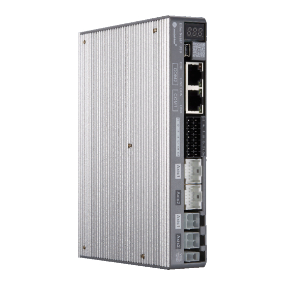
2CS3EIP Series Dual-axis EtherNet/IP Closed Loop Stepper Drive User Manual 3.3 Interface Specifications 3.3.1 Connector Definition CN5, Communication connector CN4, Digital input and output connector CN3, Encoder input signals connector CN2, Motor connector CN1, Input power connector Figure 3.2: 2CS3EIP series connectors... -
Page 17: Cn1-Input Power Connector
2CS3EIP Series Dual-axis EtherNet/IP Closed Loop Stepper Drive User Manual 3.3.2 CN1-Input Power Connector Name Signal Description 24V- 48V 3.3.3 CN2-Motor Connector Name Signal Description Motor phase A+ Motor phase A- Motor phase B+ Motor phase B- 3.3.4 CN3-Encoder Input Signals Connector... -
Page 18: Cn4-I/O Signals Connector
2CS3EIP Series Dual-axis EtherNet/IP Closed Loop Stepper Drive User Manual 3.3.5 CN4-I/O Signals Connector Name Signal Description Probe (default) I-Axis1 configurable, single-ended, 12~24V HOME (default) I-Axis1 configurable, single-ended, 12~24V POT (default) I-Axis1 configurable, single-ended, 12~24V NOT (default) I-Axis1 configurable, single-ended,... -
Page 19: Cn5-Ethernet/Ip Communication Connector
In operation after establishing link Table 3.3 Link/Activity LED status 3.3.7 Micro USB Tuning Port Name Signal Reserved Data+ Data- V_Bus 3.3.8 Salve ID (Site Alias) Setting The Salve ID (also called Site Alias) of 2CS3EIP series can be set by the following... -
Page 20: Two 7-Segment
2CS3EIP Series Dual-axis EtherNet/IP Closed Loop Stepper Drive User Manual 3 methods: Setting via Rotary Switches When Object (2151h) is set to value ‘0’, user can set a value non-zero via the two rotary switches as the salve ID, activated after restarting the power supply. -
Page 21: Digital Output
2CS3EIP Series Dual-axis EtherNet/IP Closed Loop Stepper Drive User Manual 3.4.2 Digital Output Drive Side 12-24VDC Figure 3.5: Output Interface Wiring Note: (1) The power supply (12-24VDC) above is provided by user, and if the polarity of power supply is reversed, it will damage the drive. -
Page 22: Ethernet/Ip Object Dictionary
2CS3EIP Series Dual-axis EtherNet/IP Closed Loop Stepper Drive User Manual 4 EtherNet/IP Object Dictionary Each 2CS3EIP series product support two axes, except the parameters of 1000h~1FFFh are common parameters for axis1 and axis2, other parameters are working independently, the relation between these parameters show as follow:... - Page 23 2CS3EIP Series Dual-axis EtherNet/IP Closed Loop Stepper Drive User Manual Vendor ID UINT 0-32767 4321 Leadshine code Product code UINT 0-32767 8X00 Revision number UINT 0-32767 Series number UINT 0-32767 Number of Axis1 default number of 1 mapping UINT 0-32767...
- Page 24 RXPDO assign UINT 0-32767 1600 1C13 0-02 TXPDO assign UINT 0-32767 1A00 RXPDO 1C32 0-0A administrative UINT 0-32767 parameters TXPDO 1C33 0-0A administrative UINT 0-32767 parameters The parameters can be configured by master station’s PC software or Leadshine Motion Studio.
-
Page 25: Manufacture Specific Object
2CS3EIP Series Dual-axis EtherNet/IP Closed Loop Stepper Drive User Manual 4.2 Manufacture Specific Object Explanation for index and sub-index Index Sub- index Name Access for which axis 2000 For axis1 Peak current 2800 For axis2 2001 For axis1 Microstep resolution... - Page 26 2CS3EIP Series Dual-axis EtherNet/IP Closed Loop Stepper Drive User Manual But it is recommended to modify by 2829 0x608F+01 2030 Allowed max position R/W/S UINT 0~32767 4000 Count 4000 indicates the error of one turn 2830 following error pulses 2032 Distance to send "In...
- Page 27 2CS3EIP Series Dual-axis EtherNet/IP Closed Loop Stepper Drive User Manual 4003 Max speed to close brake R/W/S UINT 0-500 0.1r/s 4803 5000 0: Disabled Internal enable state UINT 0~32767 5800 1: Enabled Bit0=0: Not reach 5000 Bit0=1: Reach Reach the target state...
-
Page 28: I/O Configuration Object
(Decimal) = Output port function setting value + Output port polarity setting value. It is recommended to use Leadshine free tuning software MotionStudio for parameter settings, which will be very simple. In Leadshine MotionStudio, digital input (DI) and digital output (DO) are displayed as SI and SO. -
Page 29: Input Ports Filter Time & Polarity Value
2CS3EIP Series Dual-axis EtherNet/IP Closed Loop Stepper Drive User Manual Note: (1) Read State2: when inputs function is valid, at this time, it has nothing to do with which input port, bit0~bit26 of 0x60FD will change to value 1. For example: when IN5 input port is set to POT and input signal is valid, then bit0 of 0x60FD will be value 1. -
Page 30: Main Control Output Function
2CS3EIP Series Dual-axis EtherNet/IP Closed Loop Stepper Drive User Manual In-position (INP) 4 (invalid) Main control output Therefore, Value of 0x2156 (Decimal) = Output port function value + Polarity value. For Example: OUT1 needs to be set as alarm function and polarity is NC: 0x2156+01= 1+128=129(0x81) 4.3.4 Main Control Output Function... - Page 31 2CS3EIP Series Dual-axis EtherNet/IP Closed Loop Stepper Drive User Manual value ~2147483647 6864 Distance to 6067 send "In It is recommended to use this object in preference, Can R/W/S UINT 0-1000 Pulse Position" also set by 0x2032, 6867 output signal...
-
Page 32: Xml File Or Esi File
EtherNet/IP Slave Information file (XML File or ESI file) is needed to connect controller with EtherNet/IP Master. This file is provided by Leadshine, described slave device information as XML format based on EtherNet/IP specifications. Please follow the EtherNet/IP master software manual for importing method. -
Page 33: Two 7-Segment And Error Code
2CS3EIP Series Dual-axis EtherNet/IP Closed Loop Stepper Drive User Manual 5 Two 7-Segment and Error Code 5.1 Two 7-Segment 错误代码显示 2CS3EIP has two 7-Segment with a LED indicate respectively (the right LED will be on when the drive is enabled), and the contents displayed are different in the initialization status and operational status. - Page 34 2CS3EIP Series Dual-axis EtherNet/IP Closed Loop Stepper Drive User Manual Error code table 0x3FFE 0x603F Value Description Trouble Shooting Value 1. Check whether the wiring is short-circuited, or the motor is short-circuited. 0x0e0 0x2211 Over-current 2. Switch power supply alarm caused, replace other power supply for a try.
-
Page 35: Alarm Clearing
2CS3EIP Series Dual-axis EtherNet/IP Closed Loop Stepper Drive User Manual 0x82b 0x8210 Invalid input and output 0x82c 0x872C Fatal sync error 0x82d 0x872D No synchronization errors 0x82e 0x872E Synchronization period is too small 0x830 0x8730 Invalid DC synchronization configuration 0x832... -
Page 36: Common Functions
2CS3EIP Series Dual-axis EtherNet/IP Closed Loop Stepper Drive User Manual 6 Common Functions 6.1 Saving Parameters and Resetting Drive To save all storable parameters into EEPROM through Object 0x1010, need to write “0x65766173” into sub-index 01h. To reset the drive to default parameters through Object 0x1011, need to write “0x64616F6C” into sub-index 01h. - Page 37 2CS3EIP Series Dual-axis EtherNet/IP Closed Loop Stepper Drive User Manual — 6041+00 Status Word Recommend PP, PV and HOME 6064+00 Actual Position Recommend Mode General 606C+00 Actual Velocity P /S Touch Probe Control — 60B8+00 Recommend Word Touch Probe Status —...
- Page 38 2CS3EIP Series Dual-axis EtherNet/IP Closed Loop Stepper Drive User Manual Bit 2 is quick stop, trigger logic is 0 effective, notice to separate from other trigger logic. Bit 7 is error reset, trigger logic is rising edge effective.
-
Page 39: Touch Probe
2CS3EIP Series Dual-axis EtherNet/IP Closed Loop Stepper Drive User Manual 6.3 Touch Probe Touch probe function is to capture and record the actual position of the motor by using the input signal with the touch probe function. The 3CS3EIP driver has two input I/O signals to support the probe function and can be enabled at the same time. The probe function related object dictionaries are shown in Table 6.6. - Page 40 2CS3EIP Series Dual-axis EtherNet/IP Closed Loop Stepper Drive User Manual Start Start 启动 启动 60B8h- bit0/bit8 60B9h- bit0/bit8 60FDh- 60B9h- bit26/bit27 bit1/bit9 60BAh/ Latch postion1 Latch postion3 60BCh Touch Probe 探针信号 Signal Rising edge trigger under single mode 单次模式上升沿触发情况 Start 启动...
-
Page 41: Appendix A: Homing Methods
2CS3EIP Series Dual-axis EtherNet/IP Closed Loop Stepper Drive User Manual Appendix A: Homing Methods The 2CS3EIP series drives support homing method -1, -2, 1 - 14, 17 - 34, and method 35 & 37. Specific definition and the process of homing methods described below. - Page 42 2CS3EIP Series Dual-axis EtherNet/IP Closed Loop Stepper Drive User Manual 6099h -01h 6099h -02h Stal l in g Sign al Negative dir ection Positive dir ection Method -3 Method -4 requires Stalling Signal. During the motor running in negative direction, when reaching the stalling signal, it will slow down and stop, then run in reverse, at last stops.
- Page 43 2CS3EIP Series Dual-axis EtherNet/IP Closed Loop Stepper Drive User Manual 6099h -01h 6099h -02h Stal l in g Sign al Negative dir ection Positive dir ection Method -6 Method 1 requires Z signal and Negative Limit. The load is located on the right side of the negative limit switch, and the motor running in negative direction. When reaching the negative limit signal, it will slow down and stop, then run in reverse, at last stops immediately when reaching the first Z signal.
- Page 44 2CS3EIP Series Dual-axis EtherNet/IP Closed Loop Stepper Drive User Manual Method 3 , 4, 5, 6 require Z signal and Home Switch Method 3 & 4 Method 5 & 6...
- Page 45 2CS3EIP Series Dual-axis EtherNet/IP Closed Loop Stepper Drive User Manual Method 7 , 8, 9, 10 require Z signal, Home Switch or Positive Limit Method 7, 8, 9, 10 Method 11 , 12, 13, 14 require Z signal, Home Switch or Negative Limit...
- Page 46 2CS3EIP Series Dual-axis EtherNet/IP Closed Loop Stepper Drive User Manual Method 17 requires negative limit switch, and method 18 requires positive limit switch. The load is located on the right side of the negative limit switch, and the motor running in negative direction. When the motor reaching the negative limit signal for the first time, it will slow down and stop, then run in reverse, at last stops immediately when reaching the negative limit signal for the second time.
- Page 47 2CS3EIP Series Dual-axis EtherNet/IP Closed Loop Stepper Drive User Manual Method 21 & 22 Method 23, 24, 25, 26 require the home switch and positive limit switch. Method 23 & 24 & 25 & 26 Method 27, 28, 29, 30 require the home switch and negative limit switch.
- Page 48 2CS3EIP Series Dual-axis EtherNet/IP Closed Loop Stepper Drive User Manual Method 27, 28, 29, 30 Method 35 & 37 use the current position as the zero position, preferred method 37 Method 35 & 37...
-
Page 49: Appendix B: Object Dictionaries
2CS3EIP Series Dual-axis EtherNet/IP Closed Loop Stepper Drive User Manual Appendix B: Object Dictionaries Sub- Default Index Name Access Type Range Unit Remark index Value 1000 Device type UINT 0-32767 0x40912 Refer to CIA 402 profile 1001 Error register USINT 0-255 Refer to Chapter 5.1... - Page 50 2CS3EIP Series Dual-axis EtherNet/IP Closed Loop Stepper Drive User Manual TXPDO-Map Default number of 1 TXPDO-Map 01-08 UDINT 0-0xFFFFFFFF object object Default number of 2 mapping Number of sub-index UINT 0-32767 object 1A01 TXPDO-Map Default number of 2 TXPDO-Map 01-08...
- Page 51 2CS3EIP Series Dual-axis EtherNet/IP Closed Loop Stepper Drive User Manual 281D 2024 0: Open Loop Control; Control Mode R/W/S UINT 0~10 2824 2: Closed Loop Control 2025 Speed point for open loop switching closed R/W/S UINT 0~200 0.1r/s 2825 loop...
- Page 52 2CS3EIP Series Dual-axis EtherNet/IP Closed Loop Stepper Drive User Manual Control software version UINT 3100 Firmware version UINT EtherNet/IP protocol UINT version 0x3FFE+01 is the current error code 3FFE 01-0B (current alarm) or the most recent error Alarm record USINT 0~32767 code (currently no alarm);...
- Page 53 2CS3EIP Series Dual-axis EtherNet/IP Closed Loop Stepper Drive User Manual homing as limit protection ) Bit2=0: The value of current position after in position = 0x607C; 5812 Bit2=1: The value of 0x607C is used as the motion offset, and finally 0x6064 = 0;...
- Page 54 2CS3EIP Series Dual-axis EtherNet/IP Closed Loop Stepper Drive User Manual 1: PP mode, 6060 Operation USINT 0-255 3: PV mode, mode 6860 6: Home mode, 6061 Operation USINT 0-255 mode display 6861 6062 -2147483648 Position DINT Pulse command ~2147483647 6862...
- Page 55 2CS3EIP Series Dual-axis EtherNet/IP Closed Loop Stepper Drive User Manual velocity ~2147483647 6899+02 607C -2147483648 The value of difference between zero position and Home offset R/W/S DINT mechanical zero point under Homing mode ~2147483647 687C 609A -2147483648 Homing R/W/S USINT...
-
Page 56: Appendix C: Connectors
2PIN, 13A MOLEX Power&Motor 39012040 4PIN, 13A Connector for 2CS3EIP-D503, 2CS3EIP-D507 MOLEX 39000038 MOLEX 513531200 Encoder Connector MOLEX 561349000 NL22100200G0G ANYTEK I/O Connector 2*11PIN, 3.5mm Note: For 2CS3EIP Series drives, motor connector and encoder connector are on the extension cable... -
Page 57: Appendix D: Faqs
2CS3EIP Series Dual-axis EtherNet/IP Closed Loop Stepper Drive User Manual Appendix D: FAQs Communicate errors. ► If it is the first time to use this EtherNet/IP drive, check whether the version of XML file is correct. Most masters support scanning slave, it is recommended to create configuration in scanning way. - Page 58 2CS3EIP Series Dual-axis EtherNet/IP Closed Loop Stepper Drive User Manual manufacturer for default homing mode, and then check the selected homing method, the relevant parameters are correct, and the limit switch needed in the selected homing method is normal. ►...
Need help?
Do you have a question about the 2CS3EIP Series and is the answer not in the manual?
Questions and answers