Table of Contents
Advertisement
Quick Links
La Marche Manufacturing Company | www.lamarchemfg.com
LMESpro
Smart Battery/HCAP Charger
This manual is subject to change without notice. You may obtain the newest version of the manual at www.lamarchemfg.com
106 Bradrock Dr. Des Plaines, IL 60018-1967
Tel: 847 299 1188
Fax: 847 299 3061
Installation and Operation Manual
CPN 144074
Instruction Drawing Number: P25-LLMESP-01
Revision A00
1
Rev. Date: 03/21
ECN:22774
Advertisement
Table of Contents

Related Manuals for La Marche LMESpro


Summary of Contents for La Marche LMESpro
- Page 1 La Marche Manufacturing Company | www.lamarchemfg.com LMESpro Smart Battery/HCAP Charger Installation and Operation Manual This manual is subject to change without notice. You may obtain the newest version of the manual at www.lamarchemfg.com 106 Bradrock Dr. Des Plaines, IL 60018-1967...
-
Page 2: Mechanical Safety
Important Safety Instructions Before using this equipment read, all manuals and other documents related to this unit and other equipment connected to this unit. Always have a copy of a unit's manual on file nearby, in a safe place; if a replacement copy of a manual is needed, it can be found at www.lamarchemfg.com. -
Page 3: Charger Location
In the unlikely event of internal damage, please inform the carrier and contact La Marche for advice on the risk due to any damage before installing the product. Verify that you have all the necessary parts as per your order for proper assembly. -
Page 4: Table Of Contents
Reset Button ..........................11 Service ...............................12 User Serviceable Parts ........................12 Performing Routine Maintenance ....................13 Troubleshooting Procedure ......................13 Appendix A: LMESpro Technical Specifications .....................14 Appendix B: Power Cabling Guide ........................15 Appendix C: Manufacturer’s Warranty ......................16 Appendix D: Document Control and Revision History ..................17... -
Page 5: Model Scope/General Description
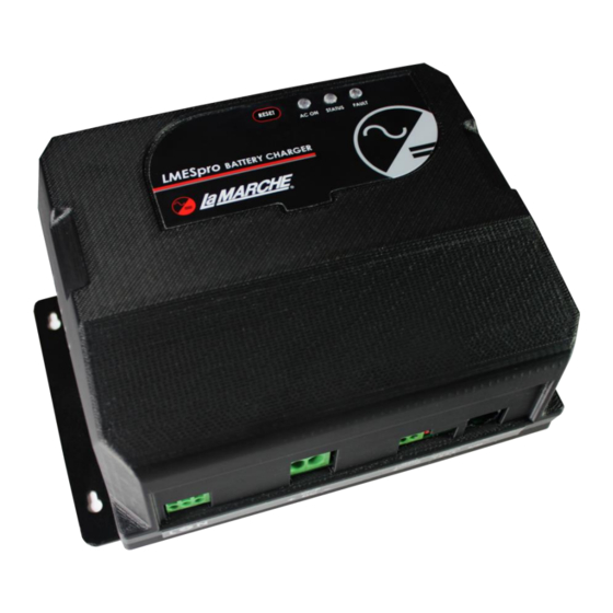
Front View Understanding the Model Number The LMESpro model number is coded to describe the options that are included. Find the model number on the nomenclature nameplate of the charger. Follow the chart to determine the configuration of your battery charger. -
Page 6: Features
Features ➢ Microprocessor Controlled High Frequency Switch-Mode Technology ➢ Single Phase Wide Range Universal AC Input: 105 Vac - 264 Vac, 50/60Hz ➢ Complete Galvanic Isolation from AC to DC ➢ Soft Start, Short Circuit Protection, Over Voltage, Over Temperature Protection, Reverse Polarity, and Input/Output Transient Overvoltage Protection ➢... -
Page 7: Installation
When mounting the LMESpro, the location chosen for the charger should be within an ambient temperature range of -40 to 122˚F (-40 to 50˚C) with a non-condensing relative humidity no higher than 95%. The LMESpro should be mounted in an area free of flammable & explosive materials and away from drips, splatter, or moving parts. -
Page 8: Electrical Connections
Local Wiring Codes must be followed. The LMESpro utilizes spring-loaded push-in style connectors. It is recommended to use wire crimp ferrules on the AC & DC field wiring when installing the charger, however it is not absolutely necessary. Crimp ferrules will prevent wire strands from fraying near the connectors. -
Page 9: 1.2.1 Ac Input Connections
Line-1 to “L” & Line-2 to “N”. • All installations require the Ground terminal to be connected to the AC service Ground/Earth wire. • All installations require 3-wire connections to the AC Input connector Figure 5 – LMESpro AC/GND Connections... -
Page 10: 1.2.2 Dc Output Connections
3/8” dia ring-terminal for connection to the battery. • Connect the crimp ferrule end of the RTS to the LMESpro. See polarity markings (++++ & - - - -) • Connect the ring-terminal to the negative terminal of the Battery/HCAP. -
Page 11: Operation
Read section 2 for Initial Setup to set the DIP switches to match the Battery/HCAP. • Read and understand all safety precautions in the manual. Apply AC power to the input terminals of the LMESpro to start up the charger after setting the DIP switches for the desired application per 2.2. DIP Switch Settings The LMESpro output can be configured to account for various battery types and voltages. -
Page 12: Lead Acid - Four Stage Charge Curve
Lead Acid - Four Stage Charge Curve Four-Stage Battery Charging Algorithm The LMESpro battery charger is designed with four stage battery charging algorithms to prevent overheating of the battery and extend the life of the lead acid battery. The four stages are: Bulk/Absorption/Float/Equalize. -
Page 13: Hcap - Four Stage Charge Curve
HCAP to climb more quickly. Once the sustained output of the LMESpro exceeds (6.1V for 12Vdc nominal or 12.2V for 24Vdc nominal), the Pre-Conditioning stage is complete, and the charger graduates to the Bulk Charge mode. (Note, in most applications, the HCAP wouldn’t regularly be discharged to a voltage that would invoke operating in... -
Page 14: Indication Details
Fault Indications and Alarms OUTPUT HIGH DC: If a 24VDC battery/HCAP is connected to the LMESpro charger when 12VDC mode is selected, the charger will shut down in high DC protection. No damage will occur to the charger. The charger will restore its output once it reaches the recovery voltage. -
Page 15: Reset Button
The Reset Button may also be used to temporarily turn-off the output circuit of the charger. While the output circuit is off, please be aware that energy is still available inside the LMESpro enclosure, the battery or HCAP where it connects to the charger, and some energy is stored in the charger’s output filter capacitors accessible on the DC output terminals. -
Page 16: Service
User Serviceable Parts Other than the AC & DC fuses, there are no user serviceable parts within the LMESpro. Only replace fuses with the same current and voltage ratings, never substitute a larger ampacity. See Figure - 13. -
Page 17: Performing Routine Maintenance
Performing Routine Maintenance Although very little maintenance is required with the LMESpro Charger, routine checks are recommended to ensure optimum system performance. Yearly 1. The charger should always be kept free of dust and debris. Remove any accumulation that may be present, particularly in the heat-sink fins near the wall. -
Page 18: Appendix A: Lmespro Technical Specifications
Appendix A: LMESpro Technical Specifications Model LMESpro (6- or 10Adc rated models available.) (6Adc: 1.5A @ 120Vac, 0.8A @ 240Vac) Input Amps Rms (Max) (10Adc: 3.3A @ 120Vac, 1.7A @ 240Vac) Input Voltage Range: 105V-264Vac, 45-65Hz AC I/P Low Cut... -
Page 19: Appendix B: Power Cabling Guide
Appendix B: Power Cabling Guide Use the following formulas and table to determine proper wire size for minimal voltage drop. At distances exceeding 10 feet, the DC wire size should be chosen to keep the voltage difference between the units DC output terminals and the battery at less than 1/2 volt when unit is fully loaded. -
Page 20: Appendix C: Manufacturer's Warranty
Should minor adjustments be required, the local La Marche sales representative should be contacted to provide this service only. All sales are final. Only standard La Marche units will be considered for return. A 25% restocking fee is charged when return is factory authorized. Special units are not returnable. -
Page 21: Appendix D: Document Control And Revision History
Appendix D: Document Control and Revision History Part Number: 144074 Instruction Number: P25-LLMESP-01 Issue ECN: 22774 22774 – 03/21...
Need help?
Do you have a question about the LMESpro and is the answer not in the manual?
Questions and answers