Table of Contents
Advertisement
Quick Links
Advertisement
Table of Contents

Subscribe to Our Youtube Channel
Related Manuals for La Marche A75D


Summary of Contents for La Marche A75D
- Page 1 MODEL A75D / A75DE SCR BATTERY CHARGER Digital METERS THREE PHASE ECN/DATE CPN124997 20535 – 8/14 20098 – 8/13 20084 – 8/13 19784 – 12/12 106 BRADROCK DRIVE DES PLAINES, IL. 60018-1967 (847) 299-1188 FAX: (847)299-3061 ISSUE DATE: ECN 19609-7/12...
-
Page 2: Important Safety Instructions
FOR THE LA MARCHE POWER CONVERSION EQUIPMENT SAVE THESE INSTRUCTIONS This manual contains important safety and operating instructions for the La Marche Power Conversion Equipment. Before using this equipment, read all instructions and cautionary markings on (1) unit, (2) battery, and (3) product using the battery. - Page 3 INSTALLATION, OPERATING AND TROUBLESHOOTING INSTRUCTIONS FOR MODEL A75D / A75DE –THREE PHASE PREPARING TO CHARGE 1. If it is necessary to remove the battery connections, always remove grounded terminal from the battery first. Make sure all loads are disconnected and unit is off, so as not to cause an arc.
-
Page 4: Receiving Instructions
NOMENCLATURE PLATES Each piece of La Marche Mfg. Equipment shipped is identified by part number on the nomenclature plate. ADJUSTMENTS All equipment is shipped from the factory fully checked and adjusted. Do not make any adjustments unless the equipment has been powered-up and the settings have been determined to be incorrect. - Page 5 INSTALLATION, OPERATING AND TROUBLESHOOTING INSTRUCTIONS FOR MODEL A75D / A75DE –THREE PHASE ***CAPACITOR PRE-CHARGE INSTRUCTIONS*** WARNING: READ INSTRUCTIONS BEFORE CONNECTING BATTERY To prevent the DC output fuse from blowing when connecting the battery, connections to the power supply and batteries should be done in the following order (single power supply).
-
Page 6: Output Ratings
+/- 0.5% regulation from no load to full load over the specified input voltage, frequency and ambient temperature range. The A75D/A75DE series is offered with DC output voltages of 24, 48 or 130VDC with output currents from 25 to 500 Amps. These chargers may be powered with 208, 240, or 480VAC. The current limit is factory set at 105% and is adjustable from 50 to 110%. -
Page 7: Mean Time Between Failure
INSTALLATION, OPERATING AND TROUBLESHOOTING INSTRUCTIONS FOR MODEL A75D / A75DE –THREE PHASE MEAN TIME BETWEEN FAILURE The mean time between failure (MTBF) in excess of 100,000 hours at 50 degrees C INPUT RATINGS AC VOLTAGE 25 Amps through 500 Amps models at 208Vac or 240Vac or 480Vac... -
Page 8: Specifications
INSTALLATION, OPERATING AND TROUBLESHOOTING INSTRUCTIONS FOR MODEL A75D / A75DE –THREE PHASE SPECIFICATIONS ELECTRICAL AC Input Voltage range +10% / -12% Frequency Range 60Hz +/- 5% DC Output 6 to 500 amps 24 or 48 or 130Vdc Output Filtering A75D NO FILTERING... -
Page 9: Relative Humidity
LOAD SHARING A load sharing circuit is provided. When connected two (2) or more A75D/A75DE units are forced to share the load equally (less than +/- 5%). To load share, connect the unit outputs (must be the same DC voltage) in parallel and connect the LS terminals together. If the charger is equipped with a Remote Equalize Terminal, connect the RE terminals together. -
Page 10: Installation Information
INSTALLATION, OPERATING AND TROUBLESHOOTING INSTRUCTIONS FOR MODEL A75D / A75DE –THREE PHASE SHOCK The battery charger in its shipping container withstands shock developed when one edge of the container is dropped six (6) inches while the opposite edge is resting on the ground, or it is dropped two (2) inches without any physical damage or degradation of the electrical performance. -
Page 11: Power Cabling Formulas
INSTALLATION, OPERATING AND TROUBLESHOOTING INSTRUCTIONS FOR MODEL A75D / A75DE –THREE PHASE POWER CABLING FORMULAS AREA SIZE AREA SIZE AREA SIZE CIR. AWG. CIR. CIR. AWG. MILS MCM* MILS MCM* MILS 1620 83690 600000 2580 105600 700000 4110 133100 750000... - Page 12 INSTALLATION, OPERATING AND TROUBLESHOOTING INSTRUCTIONS FOR MODEL A75D / A75DE –THREE PHASE NOTE: These are recommended wire size. All National and Local Wiring Codes must be followed. The table lists the AC input and the DC output minimum wire size requirements. At distances exceeding 10 feet, the DC wire size should be chosen to keep the voltage difference between the units DC output terminals and the battery at less than 1/2 volt when the unit is fully loaded.
-
Page 13: Electrical Connections & Field Wiring
LOAD SHARING A load sharing circuit is provided as a standard feature of the A75D/A75DE. When connected two (2) or more identical A75D/A75DE units are forced to share the load equally (less than +/- 5%). To load share, connect the unit outputs (must be the same DC voltage) in parallel and connect the LS terminals together. -
Page 14: Operation
INSTALLATION, OPERATING AND TROUBLESHOOTING INSTRUCTIONS FOR MODEL A75D / A75DE –THREE PHASE ALARM CONNECTIONS Form “C” contacts are provided which indicate an AC power failure and Summary Alarm. The AC failure contacts energize on alarm, the summary contacts de-energize on alarm. There is a 5 second delay on alarm. -
Page 15: Digital Display
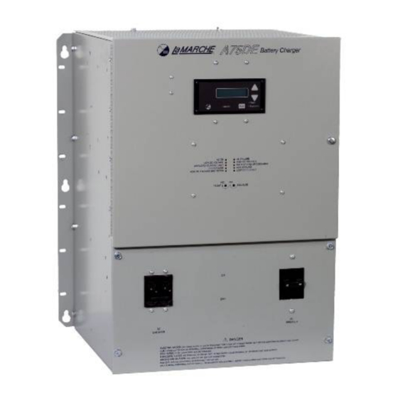
INSTALLATION, OPERATING AND TROUBLESHOOTING INSTRUCTIONS FOR MODEL A75D / A75DE –THREE PHASE DIGITAL DISPLAY OPERATION Once the proper AC input and battery are connected to the system, the digital display will indicate the system DC Output Voltage and Output Current. Pushing the "UP" button changes the display. -
Page 16: Timer Modes
INSTALLATION, OPERATING AND TROUBLESHOOTING INSTRUCTIONS FOR MODEL A75D / A75DE –THREE PHASE Contact Data: LOAD RESISTIVE LOAD (p.f. = 1) Rated load 0.60va at 120Vac 2A at 30Vdc Contact material Ag(Au clad) Carry current Max. operating voltage 125Vac 125Vdc Max. operating current Max. -
Page 17: Troubleshooting
INSTALLATION, OPERATING AND TROUBLESHOOTING INSTRUCTIONS FOR MODEL A75D / A75DE –THREE PHASE TROUBLE SHOOTING Troubleshooting should be performed only by trained service personnel or experienced electricians. CAUTION: Hazardous AC and DC voltages are present within the rectifier cabinet. EQUIPMENT: The only equipment required is a multimeter for voltage or resistance readings and analog ohmmeter... - Page 18 INSTALLATION, OPERATING AND TROUBLESHOOTING INSTRUCTIONS FOR MODEL A75D / A75DE –THREE PHASE DC Breaker Trips Possible Cause: Shorted power SCR. (repair/replace as required). Shorted battery cells or customer equipment. Shorted output cables. Capacitors not pre-charged. Loose connections on the DC fuse.
-
Page 19: General Maintenance Procedure
INSTALLATION, OPERATING AND TROUBLESHOOTING INSTRUCTIONS FOR MODEL A75D / A75DE –THREE PHASE General Maintenance Procedure Yearly 1. Blow out rectifier/inverter with a low-pressure air hose. 2. Make sure all connections are tight. 3. Perform a visual check on all internal components. -
Page 20: Manufacturer's Warranty
Special units are not returnable. In no event shall La Marche Manufacturing Co. have any liability for consequential damages, or loss, damage or expense directly or indirectly arising from the use of the products, or any inability to use them either separately or in combination with other equipment or materials, or from any other cause.
Need help?
Do you have a question about the A75D and is the answer not in the manual?
Questions and answers