Table of Contents
Advertisement
Quick Links
La Marche Manufacturing Company | www.lamarchemfg.com
SC3
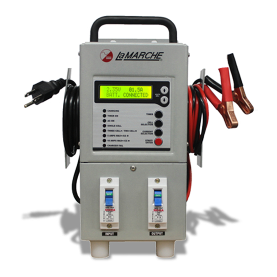
1-2-3 Cell Battery Charger
Installation and Operation Manual
This manual is subject to change without notice. You may obtain the newest version of the manual at www.lamarchemfg.com
106 Bradrock Dr. Des Plaines, IL 60018-1967
CPN 136504
Instruction Drawing Number: P25-LSC3-1
Tel: 847-299-1188
Fax: 847-299-3061
Revision A01
Rev. Date: 07/17
ECN: 21515
Advertisement
Table of Contents

Related Manuals for La Marche SC3


Summary of Contents for La Marche SC3
- Page 1 La Marche Manufacturing Company | www.lamarchemfg.com 1-2-3 Cell Battery Charger Installation and Operation Manual This manual is subject to change without notice. You may obtain the newest version of the manual at www.lamarchemfg.com 106 Bradrock Dr. Des Plaines, IL 60018-1967...
-
Page 2: Important Safety Instructions
Important Safety Instructions Before using this equipment read all manuals and other documents related to this unit and other equipment connected to this unit. Always have a copy of a units manual on file nearby, in a safe place; if a replacement copy of a manual is needed it can be found at the www.lamarchemfg.com. -
Page 3: Charger Location
In the unlikely event of internal damage, please inform the carrier and contact La Marche for advice on the risk due to any damage before installing the product. Verify that you have all the necessary parts per your order for proper assembly. -
Page 4: Table Of Contents
Performing Routine Maintenance .................... 13 Troubleshooting Procedure ...................... 13 Appendix A: SC3 Specifications ......................14 Appendix B: SC3 Current draw, Heat loss, and Case size ..............15 Appendix D: Manufacturer’s Warranty....................17 Appendix E: Document Control and Revision History ................18... -
Page 5: Sc3 General Description
Understanding the Model Number The SC3 model number is coded to describe charger and options that are included. Find the model number on the nomenclature sticker of the charger. Then follow the chart to determine configuration of your battery charger. -
Page 6: Equipment Handling
Storing the SC3 If SC3 is to be stored for more than a few days after delivery, it should be stored within its shipping container. The location chosen for storage should be within an ambient temperature of -40 to 185° F (-40 to 85° C) with a non-condensing relative humidity of 0 to 95%. -
Page 7: Installation
Installation Mounting The SC3 can be wall mounted using four #4 bolts. Install the SC3 using appropriate hardware on the wall. Figure 1 - SC3 Mounting Dimensions... -
Page 8: Electrical Connections
2.2.2 Output Connections The SC3 is equipped with Alligator clip-type terminals for the output connections. The positive cable from each battery should be connected to a separate positive DC output terminal. See figure 2. If the distance between the charger’s DC output and the battery/load exceeds 6 feet, use the Power Cable Guide in Appendix C to minimize the voltage drop across the wire distance. -
Page 9: Operation
Front Display and Indicators Close the AC breaker to power on the charger. Upon powering up the SC3, the “AC ON” indicator on the front panel will illuminate, the LCD will display the Output Voltage & Current as zero with display message “CONNECT BATTERY”. -
Page 10: Controls
3.2.2 LED Indicators LCD Display – The LCD display shows the output DC voltage and output DC amperage of the SC3 charger at all times. Chargers modes and different alarm conditions will be displayed if they should occur. Charging (Green) – The charging LED will illuminate and blink during battery charging. -
Page 11: Flow Chart
Flow Chart For configuration, follow the SC3 flow chart. Use the Up and Down buttons to cycle through the available options and the Start button to run the charger. See the chart below for the adjustable settings in the calibration mode. -
Page 12: Setting Timer
3.3.1 Setting Output Mode Press UP Button with increasing SET VOLT values. >2.25V >2.30V 06.5A 06.8A Charging Charging Press DOWN Button with decreasing SET VOLT values. >2.25V >2.20V 06.5A 06.2A Charging Charging 3.3.2 Setting Timer Press Timer button to run timer. >SET TIMER 8 HOURS Timer start from 1-24 Hours and default value is 8 hours using UP/DOWN switch. -
Page 13: Service
Before workings on SC3 charger ensure that the main breaker is at “OFF” position and the AC power if off. Disconnect the battery from the charger via the battery disconnect breaker at “OFF”... -
Page 14: Appendix A: Sc3 Specifications
Appendix A: SC3 Specifications ELECTRICAL AC Input Voltage range: 100– 150Vac Frequency Range: 45-65Hz DC Output 5A/10A @ 2.25Vdc 5A/10A @ 4.50Vdc 5A/10A @ 6.75Vdc Output Filtering Suitable for Valve-Regulated batteries ± 0.5% from no load to full load over the specified input voltage, frequency Regulation and ambient temperature range. -
Page 15: Appendix B: Sc3 Current Draw, Heat Loss, And Case Size
Appendix B: SC3 Current draw, Heat loss, and Case size No. Cell Operation Mode Input Voltage AC Current 5 A CC 120V 10 A CC 120V Single Cell 5A C.V. Mode 120V 10A C.V. Mode 120V 5 A CC 120V... - Page 16 Appendix C: Power Cabling Guide Use the following formulas and table to determine proper wire size for minimal voltage drop. At distances exceeding 6 feet, the DC wire size should be chosen to keep the voltage difference between the units DC output terminals and the battery at less than 1/2 volt when unit is fully loaded. SIZE AREA SIZE...
-
Page 17: Appendix D: Manufacturer's Warranty
In addition to the standard one (1) year warranty, La Marche warrants it’s magnetics and power diodes on a parts replacement basis only for one (1) additional year under normal use. -
Page 18: Appendix E: Document Control And Revision History
Appendix E: Document Control and Revision History Part Number: 136504 Instruction Number: P25-LSC3-1 Issue ECN: 21497 21515 - 7/17 21497 - 6/17...
Need help?
Do you have a question about the SC3 and is the answer not in the manual?
Questions and answers