Table of Contents
Advertisement
Quick Links
106 Bradrock Dr. Des Plaines, IL 60018-19671
Tel: 847 299 1188
Fax: 847 299 3061
La Marche Manufacturing Company
www.lamarchemfg.com
MXHF
MXHF
MXHF
MXHF
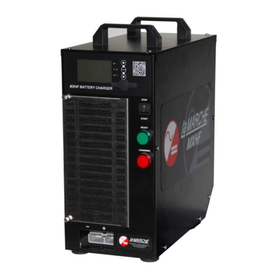
Motive Power Battery Charger
Installation and Operation Manual
CPN 128964
Instruction Drawing Number: P25-LMXHF-1
Revision A00
Rev. Date: 03/14
ECN: 20355
Advertisement
Table of Contents

Subscribe to Our Youtube Channel
Related Manuals for La Marche MXHF


Summary of Contents for La Marche MXHF
- Page 1 La Marche Manufacturing Company www.lamarchemfg.com MXHF MXHF MXHF MXHF Motive Power Battery Charger Installation and Operation Manual 106 Bradrock Dr. Des Plaines, IL 60018-19671 CPN 128964 Instruction Drawing Number: P25-LMXHF-1 Tel: 847 299 1188 Fax: 847 299 3061 Revision A00 Rev.
-
Page 2: Important Safety Instructions
Important Safety Instructions Before using this equipment read all manuals and other documents related to this unit and other equipment connected to this unit. Always have a copy of a units manual on file nearby, in a safe place; if a replacement copy of a manual is needed it can be found at the www.lamarchemfg.com. -
Page 3: Unit Location
In the unlikely event of internal damage, please inform the carrier and contact La Marche for advice on the risk due to any damage before installing the product. Verify that you have all the necessary parts per your order for proper assembly. -
Page 4: Table Of Contents
Model Scope/General Description ......................6 Understanding the Model Number ......................6 Equipment Handling ......................... 7 Storing the MXHF........................7 Placement of the MXHF ....................... 7 Installing the MXHF .......................... 8 Mounting the MXHF........................8 Making the AC Input Connections ....................9 2.2.1... - Page 5 Charger Interface Tabs .......................19 3.8.5 Charge Profile Factory Settings ....................20 3.8.6 Alarm Factory Settings ......................22 Service............................23 Maintenance..........................23 Troubleshooting.........................24 Appendix A: Manufacturer’s Warranty ......................26 Appendix B: MXHF Specifications......................27 Appendix C: AC Current Draw .........................28 Appendix D: Glossary..........................29 Appendix E: Document Control and Revision History..................31...
-
Page 6: Model Scope/General Description
The La Marche model MXHF is a high frequency battery charger designed for use in industrial applications. The MXHF is offered with DC output voltages of 24, 36 and 48VDC with output currents of 60, 120 and 180ADC. These chargers may be powered with 208-240VAC single phase or three phase. For 380-480VAC three phase only. -
Page 7: Equipment Handling
Storing the MXHF If the MXHF is to be stored for more than a few days after delivery, it should be stored within its shipping container. The location chosen for storage should be within an ambient temperature of -20°C to +70°C with a non-condensing relative humidity of 5 to 95%. -
Page 8: Installing The Mxhf
Mounting the MXHF There is an optional universal mounting bracket that can be fixed to the base, side and rear panels of the MXHF charger. The bracket enables the charger to be screwed or bolted to the bench, wall or floor surface and helps to protect the charger against physical damage. -
Page 9: Making The Ac Input Connections
The process has been simplified using the AC filter board which is mounted inside of the MXHF. Simply remove the top cover to access the AC filter board, it includes mounting posts for bus bar selection and headers for auxiliary power supply voltage selection. -
Page 10: Auxiliary Power Supply Voltage Selection
2.2.2 Auxiliary Power Supply Voltage Selection The auxiliary plug provides AC for the Auxiliary DC Power Supply that powers the MPC35 control PCB and its associated display and indicators. Connect the plug to the appropriate header, refer to the table below. AC Input Voltage Aux. -
Page 11: Relay Configuration
All relay contacts are located on the MPC35 Controller module. To access relay connections, simply remove the right side cover of the MXHF. Always be cautious when opening up the MXHF, make sure the power is not coming into the unit. -
Page 12: Alarms
Alarms The MXHF includes comprehensive protection and alarm monitoring. The alarms are graded into Urgent and Non-urgent alarms. Urgent alarms indicate a dangerous condition that immediately stops the charge cycle. Non-urgent alarms are indicated on the LCD and are logged in the alarm log but do not actually stop the charge cycle. -
Page 13: Battery Related Alarms
2.4.2 Battery Related Alarms Over discharged Battery <Urgent> the battery is still under 1.9 V/C after 30 seconds of charge and indicates a faulty battery that needs investigation. Deeply Discharge Battery <Non-urgent> the battery initially is under 1.9 V/C but recovers within 30 seconds of the charge cycle start, this alarm normally comes up when a battery is unplugged from the lift truck and immediately plugged into the Charger. -
Page 14: Operation Of The Mxhf
3. Pushbuttons – Up, Enter and Down pushbuttons for setting manual equalize and self-test 4. QR Code – scanning the QR code brings up the MXHF product page 5. Mini USB socket – the USB port allows the PC application to talk to MPC35 controller 6. -
Page 15: Power Modules
The powerer modules are installed through the front of the housing and slide between steel guides. To access the modules simply remove the inlet filter by removing to thumb screws holding the grill to the MXHF. Each module is forced-cooled by two high-speed axial fans that are located behind the module’s plastic faceplate. -
Page 16: Stop/Start Rocker Switch
3.4.2 Stop/Start Rocker Switch Connect the battery to the charger using the supplied cable and set the toggle switch to START, make sure the big red LED lamp illuminates on the charger. 3.4.3 Charge Complete A completed charge cycle is indicated by the big green LED lamp on the charger being illuminated. 3.4.4 Fault indicators A flashing big red LED lamp indicates a non-urgent alarm has occurred during the charge cycle. -
Page 17: Lcd Display
LCD Display 3.5.1 LCD View in the Resting State During the resting state of the MXHF, either waiting for the battery to be connected or the rocker switch to be set to START position the LCD will display the settings of the charger. -
Page 18: Lcd View In The Charge Complete State
EQ/Refresh stage has Time spent in charge cycle ended timed out EQ/Refresh stage MXHF Status Indication Green OK LED is illuminated at all times whenever AC or DC power is present. Charger Conditions: • Charge active: Red LED illuminated, Red LED Lamp illuminated •... -
Page 19: Mpc35 Controller Module
MPC35 Controller Module The MPC35 controller module provides the overall intelligence of the MXHF. It is the job of the controller to tell the power modules how to correctly charge a battery. The controller must be configured to match a certain battery before the charger can be used. -
Page 20: Charge Profile Factory Settings
Charger Tabs Battery Module Tabs Charger Status – View recent charge cycles for Battery Module Monitoring – Monitors battery insight into the health and usage of the battery. If status via a battery module. The monitoring the charger is used to charge multiple batteries, includes present battery voltage, mid-point voltage, the battery ID can be selected. - Page 21 Charge Profile Name: GEL Charge Profile Type: IUI Stage 1 Current: 16A / 100Ah (100%) Stage 2 Voltage: 2.35 V/C Stage 3 Current: 0.96A / 100Ah (6%) Stage 3 Min dV/dt: 3mV/15min/cell Stage 3 Max Cell Voltage: 2.6 V/C Stage 1 Timeout: 360 minutes Stage 2 Timeout: 270 minutes Stage 3 Timeout: 180 minutes EQ/Refresh Current: 0.48A / 100Ah (3%)
-
Page 22: Alarm Factory Settings
3.8.6 Alarm Factory Settings Charger Related Alarms Main Switch Non-Urgent Module Fail Configuration Error APC Communication Fail Inlet Filter Urgent Module Fail Output Fuse APC Voltage Imbalance Low Mains Module Fan Fail No Output Current APC Electrolyte Low Mains Fail Module Over Temperature Controller ADC Fail Daily Schedule Stop... -
Page 23: Service
Service All work inside the MXHF should be performed by a qualified technician. La Marche is not responsible for any damages caused by an unqualified technician. Maintenance The charger, provided it’s installed correctly in an appropriate location and is not abused, will require little maintenance. -
Page 24: Troubleshooting
Troubleshooting Problem Possible Cause Remedy Main Switch Alarm Front panel switch in the STOP Charge will start when the switch position is set to START Inlet Filter Alarm Air inlet filter blocked Clean the filter Low Mains Alarm AC mains supply is low or power Replace faulty power... - Page 25 Deeply Discharged Battery Battery is still under 1.9 V/C after Check battery for faults 30 seconds of charge Incorrect Battery Battery is not the correct voltage Check the configuration matches for the charger the battery, check the operator is not trying to plug an incorrect battery to the charger Bulk Charge Timeout The bulk charge part of the cycle...
-
Page 26: Appendix A: Manufacturer's Warranty
Special units are not returnable. In no event shall La Marche Manufacturing Co. have any liability for consequential damages, or loss, damage or expense directly or indirectly arising from the use of the products, or any inability to use them either separately or in combination with other equipment or materials, or from any other cause. -
Page 27: Appendix B: Mxhf Specifications
Appendix B: MXHF Specifications ELECTRICAL Single or Three Phase AC Input Voltage Range 175-300VAC, or 340-530VAC (Three Phase Only) Frequency Range 45-65Hz ± 5% 60, 120, 150, or 180 ADC DC Output 24, 36, or 48VDC <2mV Output Filtering ± 0.05% from no load to full load over the specified input voltage, frequency and Regulation ambient temperature range. -
Page 28: Appendix C: Ac Current Draw
16.2 11.5 18.5 13.5 20.8 17.3 12.2 19.9 14.5 22.3 25.9 12.6 20.8 15.3 23.4 27.2 Note: The light highlighted cells represent two power modules installed inside the MXHF, the dark highlighted cells represent MXHF with three power modules installed. -
Page 29: Appendix D: Glossary
Appendix D: Glossary Analog Digital Converter, internal controller hardware convert measurements into digital signals for processing. Battery that the electrolyte is held in separators between the plates, fitted with a pressure relief value so it only vents under unusual circumstances. Auto EQ/Refresh After It’s the time the battery needs to remain connected to the charger to initiate a refresh cycle. - Page 30 NET Framework Microsoft library of pre coded solutions required for the MMPC Interface software to run. SB350 350A Anderson Power connector type SB. Temp Comp Temperature compensation where the charging voltage is adjusted for the ambient temperature operating conditions. Termination When the charge cycle completes.
-
Page 31: Appendix E: Document Control And Revision History
Appendix E: Document Control and Revision History Part Number: 128964 Instruction Number: P25-LMXHF-1 Issue ECN: 20355 – 03/14...
Need help?
Do you have a question about the MXHF and is the answer not in the manual?
Questions and answers