Table of Contents

Related Manuals for Unitech UT-201


Summary of Contents for Unitech UT-201
- Page 1 INSTRUCTION MANUAL Model No. : UT-201 DUAL CHANNEL UNIVERSAL PROCESS INDICATOR / CONTROLLER 201.0 RL-2 RL-1 201.0 RL-3 RL-4 www.utplindia.in 96 x 96 Flame Proof www.utplindia.in +91 7046223333 , 9427301436 sales@utplindia.in...
- Page 2 12 / 24 VDC – a switch, fuse (1A, 125A) or a circuit breaker. The above items should be installed together with UT-201 for the products electrical protection. The switch, Fuse or circuit-breaker should be located close to the controller, within easy reach operator.
-
Page 3: Table Of Contents
UNIVERSAL PROCESS INDICATOR & CONTROLLER UT-201 CONTENTS OVERVIEW ....................INTRODUCTION ..................INSTALLATION ........................................MOUNTING ....................EXTERNAL DIMENSION ....................TECHNICAL SPECIFICATIONS ....................WIRING DIAGRAM PROGRAMMING ..................................OPERATION INTERFACE ..............MODE ACCESS FLOW CHART OPERATIONAL MODES ................................CONFIGURATION MODE .................... -
Page 4: Overview
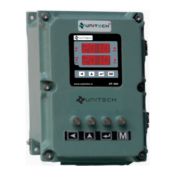
Introduction Function Unitech’s UT-201 Dual Channel Universal Indicator is designed to accept 2 Nos. thermocouple or RTD or Linear Input and displays the process parameter through a dual set of 4 Digit Red LED Displays. The instrument is available in a panel mounted housing which requires a cut out as per Panel cutout Dime- - nsions given later . -
Page 5: Technical Specifications
UNIVERSAL PROCESS INDICATOR & CONTROLLER UT-201 Technical Specifications TECHNICAL SPECIFICATIONS K, J, R, S, T, E Pt-100, Pt-1000, Cu-53 [2 wire, 3 wire] Type of Input CURRENT [Analog] Linear : 4 ~20mA DC, 0~20mA DC, 0 ~5 Amp AC [Ch-1 & Ch-2] VOLTAGE [Analog] Linear : 0.5~2.5VDC, 1~5VDC, 0~10VDC... -
Page 6: Wiring Diagram
UNIVERSAL PROCESS INDICATOR & CONTROLLER UT-201 Wiring Diagram 1 2 3 4 5 6 7 8 9 24VDC CAUTION CH:1 INPUT WIRING CONSIDERATION Shielded twisted pair wire is used for all analog I/P, Process sensors RTD, Thermo-couple, mV-mA DC, Volt DC, Linear input and Communication. -
Page 7: Programming
UNIVERSAL PROCESS INDICATOR & CONTROLLER UT-201 PROGRAMMING Operation Interface FRONT VIEW CH:1 PV Display 8.8.8.8. 2 0 1.1 Relay-2 LED Relay-1 LED RL-2 RL-1 CH:2 PV Display 8.8.8.8. 2 0 1.2 COM LED PASS Key MODE Key UP Key ENTER Key www.utplindia.in... -
Page 8: Mode Access Flow Chart
UNIVERSAL PROCESS INDICATOR & CONTROLLER UT-201 Mode Access Flow Chart. Setup Configuration Change Calibration Mode Mode Mode Password Mode Normal Mode 8888 MODE MODE MODE MODE CH:1 8888 COnf SETP CPAS CH:2 Mode Selection pass pass pass pass Press key to enter into the... -
Page 9: Operational Modes
UNIVERSAL PROCESS INDICATOR & CONTROLLER UT-201 OPERATIONAL MODES Configuration Mode ‘Configuration Mode’ will shown by pressing key in the Normal mode.. Display Parameter Range / Values CONFIGURATION MODE PASSWORD Range : Values between 0000 to 9999 pass Password for Config. Mode Parameters... - Page 10 UNIVERSAL PROCESS INDICATOR & CONTROLLER UT-201 Continue Configuration Mode Display Parameter Range / Values : Active in Low ALARM 3 & 4 RELAY ACTION Values : L oN tsp3 & Alarm Relay activation direction same as AL 1&2 : Active in High...
-
Page 11: Setup Mode
UNIVERSAL PROCESS INDICATOR & CONTROLLER UT-201 Setup Mode ‘Setup Mode’ Mode will shown by pressing key, after Conf Mode display. Display Parameter Range / Values SETUP MODE PASSWORD Range : Values between 0000 to 9999 pass Password for Setup Mode Parameters... -
Page 12: Calibration Mode
UNIVERSAL PROCESS INDICATOR & CONTROLLER UT-201 Calibration Mode ‘Calibration Mode’ Mode will shown by pressing key, after Setp Mode display. Display Parameter Range / Values CALIBRATION MODE PASSWORD Range : Values between 0000 to 9999 pass Password for Calibration Mode Parameters... -
Page 13: Change Password Mode
UNIVERSAL PROCESS INDICATOR & CONTROLLER UT-201 Change Password Mode ‘Change Password Mode’ Mode will shown by pressing key, after CAL Mode display. Display Parameter Range / Values CHANGE PASSWORD MODE PASSWORD Range : Values between 0000 to 9999 PAsS Password for Change Password Mode. -
Page 14: Communication [Modbus Rtu] Protocol
RS-485 RS-232 DATA+ RS-485 BUS Ethernet DATA- CONVERTER UNITECH TECHNOCRATS PVT LTD www.utplindia.in All content are subject to change without notice FACTORY:- 78/1/Z/3-Makarpura G.I.D.C., due to continuous improvements. +91 7046223333 , 9427301436 N/R Vadasar Bridge. O/p-Gayatri Temple Doc. Ref. 1410/R04/0819 VADODARA - 390010.
Need help?
Do you have a question about the UT-201 and is the answer not in the manual?
Questions and answers