Table of Contents

Related Manuals for Unitech UT-102


Summary of Contents for Unitech UT-102
- Page 1 INSTRUCTION MANUAL Model No. : UT-102 UNIVERSAL PROCESS INDICATOR / CONTROLLER 102.0 RL-2 RL-1 102.0 RL-3 RL-4 www.utplindia.in 96 x 96 Flame Proof www.utplindia.in +91 7046223333 , 9427301436 sales@utplindia.in...
- Page 2 12 / 24 VDC – a switch, fuse (1A, 125A) or a circuit breaker. The above items should be installed together with UT-102 for the products electrical protection. The switch, Fuse or circuit-breaker should be located close to the controller, within easy reach operator.
-
Page 3: Table Of Contents
UNIVERSAL PROCESS INDICATOR & CONTROLLER UT-102 CONTENTS OVERVIEW ....................INTRODUCTION ..................INSTALLATION ........................................MOUNTING ....................EXTERNAL DIMENSION ....................TECHNICAL SPECIFICATIONS ....................WIRING DIAGRAM PROGRAMMING ..................................OPERATION INTERFACE ..............MODE ACCESS FLOW CHART OPERATIONAL MODES ................................CONFIGURATION MODE .................... -
Page 4: Overview
Parameters can also be hidden to user to prevent improper configuration of the unit Mount Anywhere The UT-102 product group is Process control instruments that must be panel mounted. The wiring terminals must be provided. the UT-102 is environmentally hardened and, if suitably handled, can be mounted virtua- -lly anywhere in plant or factory;... -
Page 5: Technical Specifications
UNIVERSAL PROCESS INDICATOR & CONTROLLER UT-102 Technical Specifications TECHNICAL SPECIFICATIONS K, J, R, S, T, E Pt-100, Pt-1000, Cu-53 [2 wire, 3 wire] Type Of Input CURRENT [Analog] Linear : 4 ~20mA DC, 0~20mA DC, 0 ~5 Amp AC VOLTAGE [Analog] Linear : 0.5~2.5VDC, 1~5VDC, 0~10VDC... -
Page 6: Wiring Diagram
UNIVERSAL PROCESS INDICATOR & CONTROLLER UT-102 Wiring Diagram 1 2 3 4 5 6 7 8 9 OUTPUT 24VDC (Analog Out) CAUTION WIRING CONSIDERATION Shielded twisted pair wire is used for all analog I/P, Process sensors RTD, Thermo-couple, mV-mA DC, Volt DC, Linear input and Communication. -
Page 7: Programming
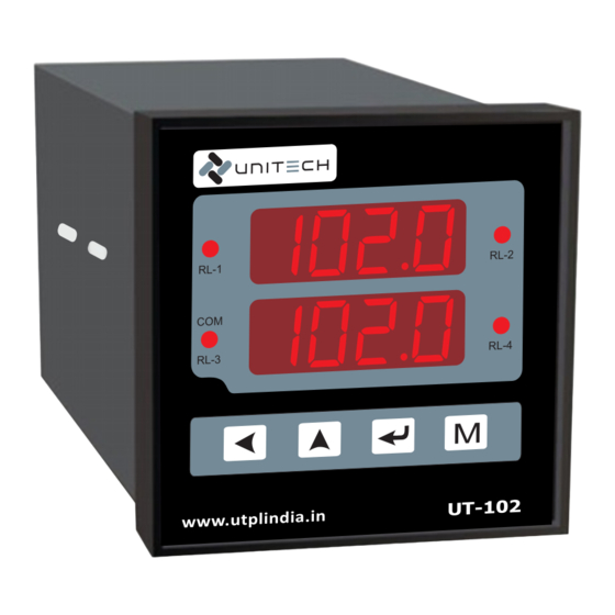
UNIVERSAL PROCESS INDICATOR & CONTROLLER UT-102 PROGRAMMING Operation Interface FRONT VIEW Present Value Display 8.8.8.8. 1 0 0.0 Relay-2 LED Relay-1 LED RL-2 RL-1 Set Value Display 8.8.8.8. 1 0 0.0 Relay-3 LED Relay-4 LED COM LED RL-3 RL-4 PASS Key... -
Page 8: Mode Access Flow Chart
UNIVERSAL PROCESS INDICATOR & CONTROLLER UT-102 Mode Access Flow Chart. Configuration Setup Change Calibration Mode Mode Mode Password Mode Normal Mode 8888 MODE MODE MODE MODE 8888 COnf SETP CPAS Mode Selection pass pass pass pass Press key to enter into... -
Page 9: Operational Modes
UNIVERSAL PROCESS INDICATOR & CONTROLLER UT-102 OPERATIONAL MODES Configuration Mode ‘Configuration Mode’ will shown by pressing & key simultaneously. Display Parameter Range / Values CONFIGURATION MODE PASSWORD Range : Values between 0000 to 9999 pass Password for Config. Mode Parameters... - Page 10 UNIVERSAL PROCESS INDICATOR & CONTROLLER UT-102 Continue Configuration Mode Display Parameter Range / Values DEAD BAND Values : : Selected DEAD : Not Operate Relay-1 on two setpoints Increase by key, Decrease by key. If set as YES, Only Relay-1 get operated in this...
-
Page 11: Setup Mode
UNIVERSAL PROCESS INDICATOR & CONTROLLER UT-102 Setup Mode ‘Setup Mode’ Mode will shown by pressing key, after Conf Mode display. Display Parameter Range / Values SETUP MODE PASSWORD Range : Values between 0000 to 9999 pass Password for Setup Mode Parameters... -
Page 12: Calibration Mode
UNIVERSAL PROCESS INDICATOR & CONTROLLER UT-102 Calibration Mode ‘Calibration Mode’ Mode will shown by pressing key, after Setp Mode display. Display Parameter Range / Values CALIBRATION MODE PASSWORD Range : Values between 0000 to 9999 pass Password for Calibration Mode Parameters... -
Page 13: Change Password Mode
UNIVERSAL PROCESS INDICATOR & CONTROLLER UT-102 Change Password Mode ‘Change Password Mode’ Mode will shown by pressing key, after CAL Mode display. Display Parameter Range / Values CHANGE PASSWORD MODE PASSWORD Range : Values between 0000 to 9999 PAsS Password for Change Password Mode. -
Page 14: Communication [Modbus Rtu] Protocol
RS-485 RS-232 DATA+ RS-485 BUS Ethernet DATA- CONVERTER UNITECH TECHNOCRATS PVT LTD www.utplindia.in All content are subject to change without notice FACTORY:- 78/1/Z/3-Makarpura G.I.D.C., due to continuous improvements. +91 7046223333 , 9427301436 N/R Vadasar Bridge. O/p-Gayatri Temple Doc. Ref. 1410/R04/0819 VADODARA - 390010.
Need help?
Do you have a question about the UT-102 and is the answer not in the manual?
Questions and answers