Table of Contents

Related Manuals for Unitech UT-101


Summary of Contents for Unitech UT-101
- Page 1 INSTRUCTION MANUAL Model No. : UT-101 UNIVERSAL PROCESS INDICATOR / CONTROLLER www.unitechinstrument.com RL-1 RL-2 RL-3 RL-4 96 x 96 96 x 48 48 x 96 Flame Proof www.utplindia.in sales@utplindia.in +91 7046223333 , 9427301436...
- Page 2 12 / 24 VDC – a switch, fuse (1A, 125A) or a circuit breaker. The above items should be installed together with UT-101 for the products electrical protection. The switch, Fuse or circuit-breaker should be located close to the controller, within easy reach operator.
-
Page 3: Table Of Contents
UNIVERSAL PROCESS INDICATOR & CONTROLLER UT-101 CONTENTS OVERVIEW ....................INTRODUCTION ..................NSTALLATION ........................................MOUNTING ....................EXTERNAL DIMENSION ....................TECHNICAL SPECIFICATIONS ....................WIRING DIAGRAM PROGRAMMING ..................................OPERATION INTERFACE ..............MODE ACCESS FLOW CHART OPERATIONAL MODES ................................CONFIGURATION MODE .................... -
Page 4: Overview
Parameters can also be hidden to user to prevent improper configuration of the unit Mount Anywhere The UT-101 product group is Process control instruments that must be panel mounted. The wiring terminals must be provided. the UT-101 is environmentally hardened and, if suitably handled, can be mounted virtua -lly anywhere in plant or factory;... -
Page 5: Technical Specifications
UNIVERSAL PROCESS INDICATOR & CONTROLLER UT-101 Technical Specifications TECHNICAL SPECIFICATIONS K, J, R, S, T, E Pt-100, Pt-1000, Cu-53 [2 wire, 3 wire] Linear : 4 ~20mA DC, 0~20mA DC, 0 ~5 Amp AC Type Of Input CURRENT [Analog] VOLTAGE [Analog] Linear : 0.5~2.5VDC, 1~5VDC, 0~10VDC... -
Page 6: Wiring Diagram
UNIVERSAL PROCESS INDICATOR & CONTROLLER UT-101 Wiring Diagram 96X48 & 48X96 1 2 3 4 5 6 7 8 9 10 11 CAUTION WIRING CONSIDERATION Shielded twisted pair wire is used for all analog I/P, Process sensors RTD, OUTPUT RS - 485 24VDC Thermo-couple, mV-mA DC, Volt DC, Linear input and Communication. - Page 7 UNIVERSAL PROCESS INDICATOR & CONTROLLER UT-101 1 2 3 4 5 6 7 8 9 Wiring Diagram 96X96 OUTPUT 24VDC (Analog Out) UT-101 [96x96] SUPPLY 230 15VAC 24 / 12 VDC RELAY-2 RELAY-1 SUPPLY 10 11 AC SUPPLY DC SUPPLY...
-
Page 8: Programming
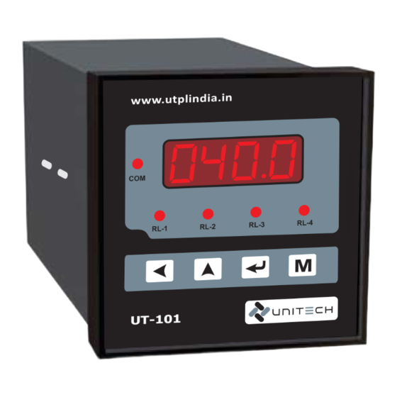
UNIVERSAL PROCESS INDICATOR & CONTROLLER UT-101 PROGRAMMING Operation Interface www.utplindia.in 3 / 6 RL-1 RL-2 RL-3 RL-4 UT-101 FRONT VIEW NORMAL VIEWS 1. 7 segment Display 4 Digit 7 segment dedicated to display the present value. In Programing mode it shows Parameter and its value. -
Page 9: Mode Access Flow Chart
UNIVERSAL PROCESS INDICATOR & CONTROLLER UT-101 Mode Access Flow Chart. Setup Configuration Change Calibration Normal Mode [PV] Mode Mode Mode Password Mode Mode Selection Press key to enter into the Programming mode from Normal mode Any New Password NOTE :... -
Page 10: Operational Modes
UNIVERSAL PROCESS INDICATOR & CONTROLLER UT-101 OPERATIONAL MODES Configuration Mode ‘Configuration Mode’ will shown by pressing key, will be display and then by pressing Range / Values Display Parameter CONFIGURATION MODE Range : Values between Password for Config. Mode Parameters... - Page 11 UNIVERSAL PROCESS INDICATOR & CONTROLLER UT-101 Continue Configuration Mode Range / Values Display Parameter DEAD BAND Values : : Selected : Not Operate Relay-1 on two setpoints Increase by key, Decrease by key. If set as , Only Relay-1 get operated in this...
-
Page 12: Setup Mode
UNIVERSAL PROCESS INDICATOR & CONTROLLER UT-101 Setup Mode ‘Setup Mode’ Mode will shown by pressing key, after Mode display. Range / Values Display Parameter SETUP MODE Range : Values between Password for Setup Mode Parameters Scroll the digit by key, Increase by key. -
Page 13: Calibration Mode
UNIVERSAL PROCESS INDICATOR & CONTROLLER UT-101 Calibration Mode ‘Calibration Mode’ Mode will shown by pressing key, after Mode display. Range / Values Display Parameter CALIBRATION MODE Range : Values between Password for Calibration Mode Parameters Scroll the digit by key, Increase by key. -
Page 14: Change Password Mode
UNIVERSAL PROCESS INDICATOR & CONTROLLER UT-101 Change Password Mode ‘Change Password Mode’ Mode will shown by pressing key, after Mode display. Range / Values Display Parameter CHANGE PASSWORD MODE Range : Values between Password for Change Password Mode. Scroll the digit by key, Increase by key. -
Page 15: Communication [Modbus Rtu] Protocol
DATA+ RS-485 BUS Ethernet DATA- CONVERTER www.utplindia.in UNITECH TECHNOCRATS PVT LTD All content are subject to change without notice FACTORY:- 78/1/Z/3-Makarpura G I D C .., due to continuous improvements. +91 7046223333 , 9427301436 N/R Vadasar Bridge. /p-Gayatri emple Doc.
Need help?
Do you have a question about the UT-101 and is the answer not in the manual?
Questions and answers