Table of Contents
Advertisement
Quick Links
Installation Instructions
4G Cellular Intercom
Part No. 4400
PROFESSIONAL INSTALL ONLY
Tip: Site Survey BEFORE you begin.
See Page 4!
FAAC International Inc.
FAAC International Inc.
v1.0
West Coast Operations
Headquarter & East Coast Operations
357 South Acacia Avenue
3160 Murrell Rd
Fullerton, CA 92831
Rockledge, FL 32955
Tel. 800 221 8278
www.faacusa.com
P a g e
| 1
Advertisement
Table of Contents

Subscribe to Our Youtube Channel
Related Manuals for FAAC 4400


Summary of Contents for FAAC 4400
- Page 1 Installation Instructions 4G Cellular Intercom Part No. 4400 PROFESSIONAL INSTALL ONLY Tip: Site Survey BEFORE you begin. See Page 4! FAAC International Inc. FAAC International Inc. v1.0 West Coast Operations Headquarter & East Coast Operations 357 South Acacia Avenue 3160 Murrell Rd...
- Page 2 Index Section Pages PHASE 1 – SITE SURVEY 3 - 4 Site Survey PHASE 2 – PRODUCT OVERVIEW 5 - 10 More Detail…. PCB Module Overview 7 - 8 Technical Specifications 9 - 10 PHASE 3 – SETUP & PROGRAMMING 11 - 17 Inserting the SIM &...
- Page 3 PHASE Site Survey P a g e...
- Page 4 Important things you Need to Know… Please read this entire manual before installing To be installed by certified and qualified this product. personnel / gate automation dealer only. Not for DIY install! Set up, on a bench in the workshop BEFORE Ensure there is a good 4G signal on site.
- Page 5 PHASE Product Overview P a g e...
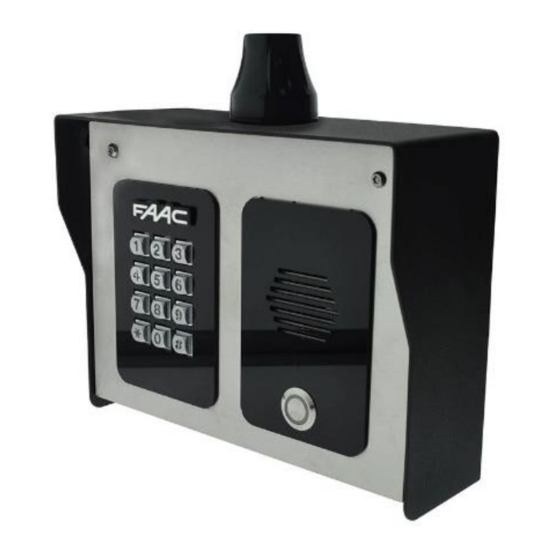
- Page 6 More Detail…. Pedestal Version Antenna Security Screws Microphone Speaker Module Push Keypad Button Antenna Pedestal Mounting Holes Surge PCB Call Button US B Cellular Module Keypad P a g e...
- Page 7 Main Cellular Module in Detail… NANO SIM Green LED = CPU Status holder Blue LED = Signal Status Female SMA Antenna Connection Red LED = Power Microphone Speaker USB-B Port Relay 1 Relay 2 DC 24V 12V DC OUT OPEN Input from 12V DC OUT Output 100mA...
- Page 8 Overview of Surge PCB Earth Rod MUST be connected for warranty. 250v 1 Amp 5x20mm Quick Blow Input Fuse (REPLACEABLE) 24v Output via flex cable to main PCB NOT USED 24v INPUT – Use provided power supply or hook up to 24v solar system.
-
Page 9: Technical Specifications
Technical Specifications GENERAL Front Panel PED = Pedestal Surface Mount. Powder Coated Marine Grade Stainless Steel BS316 Front Plates with 3mm Acrylic on Design Marine Grade Stainless Steel BS316 Modular Plates Hood Cover (MOD, IB(K), Powder coated Aluminium PED) Mounting Housing (Backbox) Marine Grade Stainless Steel BS316 Mounting Type Surface Mounted... - Page 10 RF Output Power (EIRP) 32.55dBm (GSM 900), 29.73dBm (DCS 1800) 23.77dBm (WCDMA Band I), 23.78dBm (WCDMA Band VIII) 22.79dBm, 22.73dBm, 22.97dBm, 22.35dBm, 22.99dBm (LTE B1, B3, B7, B8, B20) PROX TAGS Dimensions 40 x 25 x 4.5mm Frequency 125 KHz Type Passive, fixed 10 digit.
-
Page 11: Setup And Programming
PHASE Setup & Programming (To be done before installing the intercom) P a g e | 11... -
Page 12: Inserting The Sim Card
Inserting the SIM card Please ensure the SIM card is a 4G NANO SIM card. Do not use a SIM card for a tablet, as these only support data, and do not support voice and SMS. You simply require a mobile phone type SIM card. If using a different sim card from the one provided refer to the Cellular Coverage / APN section at the end of this document (Pages 34 –... -
Page 13: Status Leds
Status LEDs The CPU, signal strength and power status LEDs are underneath the modem and so the diagram below shows the board without the modem for convenience. Flashing = standby Constant ON/OFF = busy SIGNAL STRENGTH 1 flash = poor (1 bar) 2 flashes = low (2 bars) 3 flashes = good (3 bars) 4 flashes = Strong (4 bars) - Page 14 Using the AES PRO App Getting Started Download the App and Accept all permissions when the app is opened Choose your language Register your details P a g e | 14...
- Page 15 Sign in using previously registered email and password Device Setup Choose your device from the list provided Enter the information required to set up the device (This process can take up to 7 screens) P a g e | 15...
- Page 16 Additional App Configuration/Help Customise Advanced Features For more guidance, please see page 17 Add additional app users If you are having trouble the help section has troubleshooting and How to Videos to help you resolve the problem P a g e | 16...
- Page 17 Using the AES PRO App Due to the extensive number of features included in the app we would recommend watching the selection of YouTube videos detailing the features of the app pertaining to your intercom. Hold phone camera over the QR code This QR code will take you directly to the Prime playlist on AES’...
-
Page 18: Using The Intercom
PHASE Using the Intercom (Only to be done after the unit is successfully programmed) P a g e | 18... -
Page 19: Calling A Resident
Calling a Resident Press call button Tip: Press the call button again to cancel a call Using Keypad Codes & Prox IDs (Keypad / Prox Units) 1: Enter 4 digit code. P a g e | 19... - Page 20 Receiving A Call and Opening Gates / Door Visitors can press the call button, which will initiate a call from your intercom to the designated phone numbers which will have been programmed by your installer. 1. Visitor presses the call button or waves in front of 2.
- Page 21 Manager Controls of Gate / Door This screen allows the installer or manager to manually trigger the gate. Trigger Send trigger command [Call / SMS] Latch Hold open Gate / Door [SMS] unlatch Release held open gates to close. [SMS] Output Options P a g e | 21...
- Page 22 PHASE Installation P a g e | 22...
- Page 23 How to Achieve & Maintain IP55 Rating The IP55 rating attached to this unit is only achieved if the below steps have been followed. This is to prevent any unwanted water and/or bug ingress that can cause various issues with functionality and will void the warranty if not followed. Step 1 –...
-
Page 24: Solar Power
Power This intercom comes with a 24V dc power supply. The intercom requires up to 2 amps peak demand at times, therefore power cable is of extreme importance. Using insufficient power cable thickness will cause excessive stress on electronic components and can therefore void the manufacturer’s warranty. - Page 25 Relay Wiring Examples Driveway Gates Gate Controller Relay1 Note: manufacturer is Optional Separate not responsible lock PSU Exit Button Relay 2 for wiring to PRESS third party TO EXIT devices. Please consult the device instructions if having issues. Magnetic Lock Additional Wiring Tips Relay STRIKE...
- Page 26 PHASE Aftercare P a g e | 26...
-
Page 27: Complete List Of Parameters
Complete List of Parameters For a complete list of programming SMS parameters go to the following website: https://aesglobalparts.com/pages/gsm-resources-1 Troubleshooting Q. The unit will not power up. No LEDs on. A. Check power supply voltage at intercom is 23.4v DC or more. Cable length from PSU to intercom should be less than 25 feet and in 14 gauge for longer distances. - Page 28 Q. The audio quality that can be heard on the remote telephone is poor or humming (buzzing). A. A small amount of cellular buzz can be considered normal on cellular intercoms, but not so much that causes an inability to hear the person speaking. This is a symptom of poor reception. Try the above steps on checking and improving reception.
-
Page 29: Firmware Updates
Firmware Updates FOTA (Firmware Over The Air) FOTA allows you to update your intercom wirelessly without a PC. FOTA Intercom 9999#70BinFile# 1 2 3 9999#70BinFile# 4 5 6 7 8 9 REQUEST 9999#70X# Tip: Passcode Bin File Link Set APN before sending FOTA SMS! Command (Firmware Update) -
Page 30: App Updates
App Updates We will continually monitor the app’s performance and will release updates to enhance the user's experience and/or fix any issues that arise over time. These updates will be available via the iOS app store or the Android Play store. Enabling auto updates is recommended for the most up to date experience. - Page 31 Page Left Blank P a g e | 31...
-
Page 32: Cellular Coverage
Cellular Coverage Before installing this system, you need to be sure that there is good cellular coverage in the area it is to be installed. It is recommended that you conduct a site survey, and check reception on the site for cellular coverage. If reception is poor in the area, then this system is not recommended. - Page 33 Checking Signal Level and APN When the green and white status LEDs (shown on previous page) flash to indicate network connection, the SMS string *20# can be sent to the intercom to check the signal level and APN. Check Signal Level: The intercom should then reply with a signal level between 1 and 31.
- Page 34 LIMITED WARRANTY FAAC International, Inc. (“Seller”) warrants the first Purchaser of the product to be free from for a specific period as defined below (“Warranty Period”). defects in material and workmanship The Warranty Period commences from the date of invoice.
- Page 35 constitute an admission by the Seller of any legal responsibility to effect such replacement to make such repair, or otherwise. All products sold by the Seller are subject to design and/or appearance modifications, which are production standards at the time of shipment. The Seller may, but shall not be required to, modify or update products shipped prior to a current production standard.
-
Page 36: Regulatory Compliance
Regulatory Compliance FCC ID : 2ALPX-PRIME7-4GQA Grantee: Advanced Electronic Solutions Global LLC This device complies with Part 15 of FCC rules. Operation is subject to the following two conditions: (1) this device may not cause harmful interference, and (2) this device must accept any interference received, including interference that may cause undesired operation.
Need help?
Do you have a question about the 4400 and is the answer not in the manual?
Questions and answers