Table of Contents
Advertisement
Installation Instructions
PROFESSIONAL INSTALL ONLY
Do NOT give this manual to end user!
FAAC International Inc.
Headquarter & East Coast Operations
3160 Murrell Rd
Rockledge, FL 32955
Tel. 800 221 8278
www.faacusa.com
1 |
P a g e
FAAC-Pro 2-4GA
FAAC International Inc.
West Coast Operations
357 South Acacia Avenue
Fullerton, CA 92831
Advertisement
Table of Contents

Related Manuals for FAAC FCI4000


Summary of Contents for FAAC FCI4000
- Page 1 Installation Instructions FAAC-Pro 2-4GA PROFESSIONAL INSTALL ONLY Do NOT give this manual to end user! FAAC International Inc. FAAC International Inc. West Coast Operations Headquarter & East Coast Operations 3160 Murrell Rd 357 South Acacia Avenue Rockledge, FL 32955 Fullerton, CA 92831 Tel.
-
Page 2: Table Of Contents
Index Section Pages Site Survey Overview of Product Modem A look inside the product Power to Call Box Network Cables and Modem Power Module in Detail Main Intercom Module in Detail Keypad Module in Detail Relay Wiring Tips Powering On App Setup &... -
Page 3: Site Survey
Site Survey YES! I have 4G signal at the gate with my phone! If not, STOP. You will need some! Try a different network provider. YES! I have at least 1 Mb UPLOAD speed. If not STOP! This system may operate intermittently remotely or have delayed PUSH notifications. -
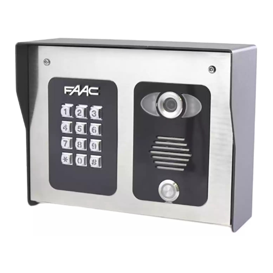
Page 4: Overview Of Product
Overview of Product Security screw access Camera Microphone Night vision LEDS (short range, up to Optional 5 feet) Keypad Speaker Call button Modem Front view Side view Mounting holes (wall or Modem pole weatherproof mountable) housing Bottom Sim Card Holder LAN RJ45 View (DATA/IOT Sim only) -
Page 5: A Look Inside The Product
Now let’s have a look inside... Pedestal mounting holes Power filter board Call button Main intercom module Speaker volume Optional keypad module Camera Code button module P a g e... -
Page 6: Power To Call Box
Power to Call Box After fitting the box to the gooseneck, re-fit the module and connect a 14-gauge earth wire to the earth terminal. IF necessary, remove 4 screws and remove the power conditioning module. Surge protected 110v Use minimum 16-gauge wire from the 24v DC adaptor provided to the terminals Call box... -
Page 7: Network Cables And Modem
Network Cables and Modem (Keep high) Modem Option 1 Perimeter wall / fence Pedestal Surge protected 110v supply 30 foot Patch cable (included) Weatherproof enclosure 6 foot patch cable (included) Perimeter wall Option 2 / fence (Mounting on Pedestal) Surge Modem + protected 110v supply... -
Page 8: Power Module In Detail
POE Power supply Main intercom Modem module WARNING: Do not send POE power to the intercom. Only the modem is powered with POE. The intercom is powered separately with 24v DC. Power Earth Rod MUST be Module in connected for warranty Detail…... -
Page 9: Main Intercom Module In Detail
RJ 45 socket for Main CAT5 Ethernet Intercom connection to router / modem Module in Quick connect terminals for Ethernet Detail... connection to router/access point/switch Code button Speaker volume 24v DC (pre-wired) from power module Relay1 Relay2 Exit button (N/O) Keypad Module in Detail…... - Page 10 Relay Wiring Tips Intercom Module Pedestrian Gate Magnetic Lock Optional Exit button (N/C) Separate Lock Power Supply Gate Controller unit Automatic Gates Note: Never connect any electric Remember to wire keypad relays to lock to the power supply provided lock or gates as well as the main with the intercom.
-
Page 11: Powering On
Powering on RF (signal level) SIM – The sim LED will come on if there is a sim inserted. RF – The first LED will flash if you have low 3G signal. The first LED will stay solid if you have low 4G signal. The second LED will flash if you have medium 3G signal. - Page 12 Step 2 Open the APP and press the Settings button. Then press the add intercom button. Step 3 Enter the intercom Bell I.D which can be found on the main board. Enter “admin” for the main user. Enter “123456789” as the default password and press the TICK as shown.
- Page 13 Step 5 Should be Press the Video icon to showing ONLINE view live video. status. Note: at close proximity, you will experience acoustic feedback. This is normal. If you can see live video If the unit is not and hear audio, the showing online intercom has successfully you are not...
- Page 14 Alternative set-up Step 6a Remove the network/LAN cable before pressing the code button Press and HOLD the code button for more than 5 seconds and release. A tone will be heard. The intercom will now begin to transmit its own wifi network called BELL-XXXXXX (where XXXXXX is the 6 >5 seconds numerical digits from the serial ID number).
- Page 15 Step 6a, 6b, 6c After pressing SEARCH, the APP will now search for the intercom and should detect it. Step 6d, 6e Intercom ID will be auto filled. Enter “admin” for the main user. Enter “123456789” as the default password and press the TICK as shown.
- Page 16 Step 6g 60 secs.. If you can see live video and hear audio, the intercom has successfully connected to the network. Reconnect the If for some reason this network/LAN cable does not work, try connecting to the wifi Wait 60 seconds. network again and The intercom will double check the wifi...
-
Page 17: Answering On Android
Answering on Android Your phone will now Swipe down your Press the green icon to launch the app and notification banner accept. you will see a when called, and press snapshot of the visitor the Intercom at which point you can notification. -
Page 18: Answering On Apple
Answering on Apple Phone will now Swipe the Swipe green Press “VIEW” launch app notification left icon to answer Note: Various versions of IOS and Android OS will have different notification acceptance techniques. Please refer to online support for your device if needed. TIP: Make sure ringer switch is ON and volume is turned up. -
Page 19: Adding Additional App Users
Adding Additional APP Users Additional users MUST be added with individual user names. Do NOT use the same username. ADMIN Phone ADMIN Phone ADMIN Phone ADMIN Phone Enter a NEW Note how username & existing users password can be deleted New Phone New Phone New Phone... -
Page 20: Other Settings
Other Settings Add an intercom (can Check APP Ring tones Edit Intercom have up to 6 version details doors/gates calling one device) Change relay times (1- Add/edit users 9 secs) Turn off config Set time zone + mode (extra (daylight saving security) adjust) Set max monitoring... -
Page 21: Sounds, Volume And Speech
Sound, Volumes and Speech This intercom is capable of full duplex speech, which means two people can have a conversation and appear to speak at the same time. Since various manufacturers of android phones, iphones and tablets all differ in acoustic performance, and different users may require varying levels of volume on their own handset, it may be possible to setup some devices in full duplex mode but others may need to be set in half duplex mode (phone user will press to talk). -
Page 22: Using The App Usu
Using the APP Settings Thumbnail preview View Camera & Call Log (shows listen images of visitors whom calls were accepted or previewed on this If you took device. snapshots of a visitor while on a call, view them here. Home If you took video recordings of visitors, you can... -
Page 23: Keypad Programming
Keypad overview This keypad has 3 outputs, all independent from the intercom/app relays. The diagram below shows the LED indicators which indicate programming and relay status information. RED when incorrect codes entered and outputs are locked out. GREEN when output 1 activated. RED when output 2 activated. - Page 24 Enter or delete new user/Homeowner codes There are 3 groups of user codes. Group 10 for relay 1, group 20 for relay 2, and group 30 for relay 3. The programming sequence is shown below… 10= relay 1 codes Memory locations 2= add code (1000 available) 000-999 for relay 1...
-
Page 25: Using The Keypad
1) Wire a push button (or replicate with wire link) across the Egress terminal and (-)GND. 2) Switch off power for 1 minute. 3) Switch ON power. 4) during the first 60 seconds, press the EG button once to enable the function. 5) Enter the following code.. -
Page 26: Revision Changes
thin) installed from 24v video lag, voice problems, specifications shown within this adaptor to the intercom, freezing, relays not opening manual. or power adaptor too far the gate. from intercom. Additional user added Can randomly display status When an additional user was “id already in use”... - Page 27 Grantee: Advanced Electronic Solutions Global Ltd This device complies with Part 15 of FCC rules. Operation is subject to the following two conditions: (1) this device may not cause harmful interference, and (2) this device must accept any interference received, including interference that may cause undesired operation.
Need help?
Do you have a question about the FCI4000 and is the answer not in the manual?
Questions and answers