Advertisement
Quick Links
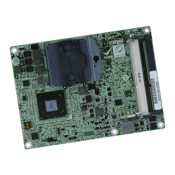
COM Express Basic Type 6 module with socket G2 supports
Intel® 2nd & 3rd generation Core™ i7/i5/i3 Celeron®
processor, VGA/LVDS, DDI, GbE, SATA 6Gb/s, USB 3.0, Audio
and RoHS
Quick Installation Guide
Package Contents
ICE-QM770 package includes the following items:
1 x ICE-QM770-R10 single board computer
1 x Heat Spreader
1 x Cooler
1 x Driver CD
1 x Utility CD
1 x QIG (Quick Installation Guide)
WARNING!
Never run the embedded module without the heat sink. The heatspreader
plate shipped with the ICE-QM770 acts as a thermal interface between the
module and the heat sink. The heat sink must be installed on the
heatspreader plate to maintain proper operating temperatures. Make sure to
maintain the heatspreader plate temperature under 60°C in operation.
©2006 Copyright by IEI Technology corp.
ICE-QM770
Version 1.00
Oct, 1, 2012
All rights reserved.
1
Advertisement

Related Manuals for IEI Technology ICE-QM770


Summary of Contents for IEI Technology ICE-QM770
- Page 1 WARNING! Never run the embedded module without the heat sink. The heatspreader plate shipped with the ICE-QM770 acts as a thermal interface between the module and the heat sink. The heat sink must be installed on the heatspreader plate to maintain proper operating temperatures. Make sure to maintain the heatspreader plate temperature under 60°C in operation.
-
Page 2: Specifications
Specifications Form Factor PICMG COM Express R2.0 Basic Type 6 Socket G2 supports Intel® 2nd & 3rd generation Core™ i7/i5/i3/Celeron® processor Intel® QM77 Memory Two 204-pin 1600/1333/1066 MHz dual-channel DDR3 SDRAM unbuffered DIMMs supported (system max. 16GB) Supports 1.35V DDR3L BIOS UEFI BIOS Graphics Engine... -
Page 3: Ordering Information
SMBus Yes (to baseboard) YYes (to baseboard) Yes (to baseboard) Expansions 1 x PCIe x16 signal (to baseboard) 7 x PCIe x1 signal (to baseboard) Watchdog Timer Software programmable supports 1~255 sec. system reset GPIO 8-bit GPIO (to baseboard) Through the baseboard Intel®... - Page 4 Table of Jumper Setting LABEL FUNCTION LCD Panel Type Setting switch 1. LVDS Panel type Selection The Panel type of LVDS can be selected by using SW1. ON=0 OFF=1 EDID Color Depth Channel 4321 Resolution 18-bit Single 0000 640X480 800X480 18-bit Single 0001...
- Page 5 Table of Connectors LABEL FUNCTION JSPI1 FLASH SPI ROM (BIOS) JSPI2 FLASH SPI ROM (EC) COM Express Connector AB COM Express Connector CD 1. Flash SPI ROM (BIOS) • JSPI1: Flash BIOS SPI ROM PIN NO. DESCRIPTION +V3.3M_SPI_CON SPI_CS SPI_SO_SW SPI_CLK_SW SPI_SI_SW 2.
- Page 6 3. COM Express Connector AB • J3: The standard COM Express connector AB location and pinouts are shown below Pin No. Description Pin No. Description GND15 GBE0_MDI3- GBE0_ACT# GBE0_MDI3+ LPC_FRAME# GBE0_LINK100# LPC_AD0 GBE0_LINK1000# LPC_AD1 GBE0_MDI2- LPC_AD2 GBE0_MDI2+ LPC_AD3 GBE0_LINK# LPC_DRQ0# GBE0_MDI1- LPC_DRQ1# GBE0_MDI1+...
- Page 7 Pin No. Description Pin No. Description USB6- USB7- USB6+ USB7+ USB_6_7_OC# USB_4_5_OC# USB4- USB5- USB4+ USB5+ GND4 USB2- USB3- USB2+ USB3+ USB_2_3_OC# USB_0_1_OC# USB0- USB1- USB0+ USB1+ VCC_RTC EXCD1_PERST# EXCD0_PERST# EXCD1_CPPE# EXCD0_CPPE# SYS_RESET# LPC_SERIRQ CB_RESET# GND5 GND20 PCIE_TX5+ PCIE_RX5+ PCIE_TX5- PCIE_RX5- GPI0 GPO1...
- Page 8 Pin No. Description Pin No. Description LVDS_A2+ LVDS_B2+ LVDS_A2- LVDS_B2- LVDS_VDD_EN LVDS_B3+ LVDS_A3+ LVDS_B3- LVDS_A3- LVDS_BKLT_EN GND10 GND23 LVDS_A_CK+ LVDS_B_CK+ LVDS_A_CK- LVDS_B_CK- LVDS_I2C_CK LVDS_BKLT_CTRL LVDS_I2C_DAT VCC5SBY1 GPI3 VCC5SBY2 RSVD VCC5SBY3 RSVD VCC5SBY4 PCIE0_CK_REF+ BIOS_DIS1# PCIE0_CK_REF- VGA_RED GND11 GND24 SPI_VCC VGA_GRN SPI_MISO VGA_BLU GPO0...
- Page 9 4. COM Express Connector CD • J4: The standard COM Express connector AB location and pinouts are shown below Pin No. Description Pin No. Description GND0 GND15 USB_SSRX0- USB_SSTX0- USB_SSRX0+ USB_SSTX0+ USB_SSRX1- USB_SSTX1- USB_SSRX1+ USB_SSTX1+ USB_SSRX2- USB_SSTX2- USB_SSRX2+ USB_SSTX2+ GND1 GND16 USB_SSRX3- USB_SSTX3-...
- Page 10 Pin No. Description Pin No. Description DDI3_AUX+ DDI1_PAIR3+ DDI3_AUX- DDI1_PAIR3- DDI3_CTRLCLK DDI3_CTRLDATA DDI3_PAIR0+ DDI2_PAIR0+ DDI3_PAIR0- DDI2_PAIR0- GND4 GND19 DDI3_PAIR1+ DDI2_PAIR1+ DDI3_PAIR1- DDI2_PAIR1- DDI3_HPD DDI2_HPD RSVD RSVD DDI3_PAIR2+ DDI2_PAIR2+ DDI3_PAIR2- DDI2_PAIR2- RSVD RSVD DDI3_PAIR3+ DDI2_PAIR3+ DDI3_PAIR3- DDI2_PAIR3- GND5 GND20 PEG_RX0+ PEG_TX0+ PEG_RX0- PEG_TX0- RSVD...
- Page 11 Pin No. Description Pin No. Description PEG_RX7- PEG_TX7- GND8 GND29 RSVD4 RSVD PEG_RX8+ PEG_TX8+ PEG_RX8- PEG_TX8- GND10 GND23 PEG_RX9+ PEG_TX9+ PEG_RX9- PEG_TX9- RSVD5 RSVD8 GND6 GND30 PEG_RX10+ PEG_TX10+ PEG_RX10- PEG_TX10- GND35 GND31 PEG_RX11+ PEG_TX11+ PEG_RX11- PEG_TX11- GND27 GND24 PEG_RX12+ PEG_TX12+ PEG_RX12- PEG_TX12- GND11...
- Page 12 Board Layout: Jumper and Connector Locations...
- Page 13 Board with Heat Spreader and Cooler dimensions:...
Need help?
Do you have a question about the ICE-QM770 and is the answer not in the manual?
Questions and answers