Table of Contents
Advertisement
Quick Links
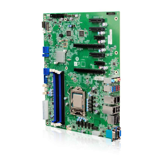
ATX Motherboard Supports 10
i9/i7/i5/i3, Celeron® and Pentium® Processors, DDR4, Triple
Independent Displays, Triple 2.5GbE, M.2, USB 3.2, SATA 6Gb/s,
Quick Installation Guide
Package List
IMBA-Q471 package includes the following items:
1 x IMBA-Q471 single board computer
2 x SATA cable
1 x I/O shielding
1 x QIG
HD Audio and RoHS
IMBA-Q471
Version 1.0
January 21, 2022
© 2022 Copyright by IEI Integration Corp.
All rights reserved.
Gen. LGA1200 Intel® Core™
th
th
/11
Advertisement
Table of Contents

Related Manuals for IEI Technology IMBA-Q471


Summary of Contents for IEI Technology IMBA-Q471
- Page 1 Independent Displays, Triple 2.5GbE, M.2, USB 3.2, SATA 6Gb/s, HD Audio and RoHS IMBA-Q471 Quick Installation Guide Version 1.0 January 21, 2022 Package List IMBA-Q471 package includes the following items: 1 x IMBA-Q471 single board computer 2 x SATA cable 1 x I/O shielding ...
- Page 2 Specifications CPU: Generation LGA1200 Intel® Core™ i9/i7/i5/i3, Celeron® and Pentium® processors Chipset: Intel® Q470 Memory: Four 288-pin 2933 MHz dual-channel unbuffered DDR4 SDRAM DIMM slots supporting up to 128 GB memory BIOS: AMI UEFI BIOS Graphics Engine: Up to Intel®...
- Page 3 1 x RS-422/485 (1x4 pin, p=2.0) 5 x SATA 6Gb/s (RAID 0/1/5/10 supported) Audio: Realtek ALC888S HD Audio codec supports 7.1-channel 3 x Audio jack (line-in, line-out, mic-in) on rear I/O 1 x Front audio (2x5 pin, p=2.54) Front Panel: 1 x Front panel (2x7 pin, p=2.54;...
- Page 4 IEI Resource Download Center All the drivers and utility for the IMBA- https://download.ieiworld.com Q471 are available on IEI Resource Download Center. Type IMBA-Q471 and press Enter to find all the relevant software, utilities, and documentation. To install software from the downloaded ISO file, mount the file as a virtual drive to view its content.
- Page 5 Ordering Information IMBA-Q471-R10: Gen. LGA1200 Intel® Core™ ATX Motherboard Supports 10 i9/i7/i5/i3, Celeron® and Pentium® Processors, DDR4, Triple Independent Display, Triple 2.5GbE, M.2, USB 3.2, SATA 6Gb/s, HD Audio and RoHS 19800-003100-100-RS: Dual port USB cable with bracket, 30mm, p=2.54 ...
-
Page 6: Table Of Contents
Jumpers Setting and Connectors LABEL FUNCTION J_ATX_AT1 AT/ATX power mode setting ME_RTC2 Clear CMOS jumper ME_RTC1 Clear ME jumper J_FLASH1 Flash descriptor security override jumper AUDIO1 Internal audio connector ATX1 ATX power connector CPU12V1 ATX CPU 12V power connector DBG_PORT1 Debug connector DIO1 Digital I/O connector... - Page 7 PWR_SW1 Onboard power button AUDIO_CV1 External HD Audio jack External dual 2.5GbE RJ-45 connector External dual USB 3.2 Gen 1 and CON1_USB1 dual USB 3.2 Gen 2 connector External 2.5GbE RJ-45 and dual USB 2.0 LAN3_USB2 combo connector COM1/VGA1 External RS-232 and VGA combo connector HDMI_DP1 External HDMI and DP++ combo connector J_ATX_AT1: AT/ATX Power Mode Setting...
- Page 8 USB Power SW: USB Power Setting USB Power SW DESCRIPTION Power is provided in S3/S4 sleep +5V DUAL state (default) Power is not provided in S3/S4 sleep state Use the USB Power SW1 and USB Power SW2 BIOS options to configure whether to provide power to the corresponding USB connector(s) when the system is in S3/S4 sleep state.
-
Page 9: Dbg_Port1
CPU12V1: ATX CPU 12V Power Connector PIN NO. DESCRIPTION PIN NO. DESCRIPTION +12V +12V +12V +12V DBG_PORT1: Debug Connector PIN NO. DESCRIPTION PIN NO. DESCRIPTION SMCLK1_EC SMDAT1_EC PLTRST_N DIO1 : Digital Input/Output Connector PIN NO. DESCRIPTION PIN NO. DESCRIPTION Output 5 Output 4 Output 3 Output 2... -
Page 10: Sys_Fan2
CPU_FAN1: CPU Fan Connector PIN NO. DESCRIPTION PIN NO. DESCRIPTION +12V FANIO SYS_FAN1: System Fan Connector PIN NO. DESCRIPTION PIN NO. DESCRIPTION FANIO SYS_FAN2: System Fan Connector PIN NO. DESCRIPTION PIN NO. DESCRIPTION +12V F_PANEL1: Front Panel Connector DESCRIPTION DESCRIPTION PWR_LED+ BEEP_PWR SPKR... -
Page 11: Led_Lan1
LED_LAN1: LAN1 Link LED Connector DESCRIPTION DESCRIPTION +3.3V LAN1_LED_LNK#_ACT LED_LAN2: LAN2 Link LED Connector DESCRIPTION DESCRIPTION +3.3V LAN2_LED_LNK#_ACT LED_LAN3: LAN3 Link LED Connector DESCRIPTION DESCRIPTION +3.3V LAN3_LED_LNK#_ACT COM3, COM4: RS-232 Serial Port Connectors PIN NO. DESCRIPTION PIN NO. DESCRIPTION COM2: RS-422/485 Serial Port Connector PIN NO. -
Page 12: S_Ata1, S_Ata2
S_ATA1, S_ATA2, S_ATA3, S_ATA4, S_ATA5: SATA 6Gb/s Connectors PIN NO. DESCRIPTION PIN NO. DESCRIPTION SATA_RX‐ SATA_TX+ SATA RX+ SATA_TX‐ SMB1: SMBus Connector PIN NO. DESCRIPTION PIN NO. DESCRIPTION SMB_CLK SMB_DATA ATXPWR2: PCIe Power Connector PIN NO. DESCRIPTION PIN NO. DESCRIPTION +12V JSPI1: Flash SPI ROM Connector PIN NO. - Page 13 JUSB4, JUSB5, JUSB6: Internal USB 2.0 Connectors PIN NO. DESCRIPTION PIN NO. DESCRIPTION USB_DATA- USB_DATA+ USB_DATA+ USB_DATA- JUSB3-1: Internal USB 3.2 Gen 1 Connector PIN NO. DESCRIPTION PIN NO. DESCRIPTION USB_DATA+ USB_RX- USB_ DATA- USB_RX+ USB3_TX+ USB3_TX- USB3_ TX- USB3_TX+ USB3_RX+ USB3_DATA- USB3_RX-...
- Page 14 PETP1 PERN2 PERP2 PETN2 PETP2 DEVSLP PERN3 PERP3 PETN3 PETP3 PERST# CLKREQ PCIECLKN PEWAKE PCIECLKP Module Key Module Key Module Key Module Key Module Key Module Key Module Key Module Key PEDET +3.3V +3.3V +3.3V AUDIO_CV1: External Audio Jacks Jack Color DESCRIPTION Blue Line-in: CD/DVD or other audio source input port...
- Page 15 JP1: External 2.5GbE RJ-45 Connectors PIN NO. DESCRIPTION PIN NO. DESCRIPTION LAN1_MDI0P LAN1_MDI0P LAN1_MDI0N LAN1_MDI0N LAN1_MDI1P LAN1_MDI1P LAN1_MDI1N LAN1_MDI1N LAN1_MDI2P LAN1_MDI2P LAN1_MDI2N LAN1_MDI2N LAN1_MDI3P LAN1_MDI3P LAN1_MDI3N LAN1_MDI3N Connect 0.1uf Connect 0.1uf 2.5G_LED 2.5G_LED 1G_LED 1G_LED ACT_LED ACT_LED +3.3V +3.3V...
- Page 16 HDMI_DP1 External DP Connector PIN NO. DESCRIPTION PIN NO. DESCRIPTION LANE0P LANE3N LANE0N AUX_CTRL_DET_C LANE1P LANE1N AUXP LANE2P AUXN LANE2N LANE3P External HDMI Connector PIN NO. DESCRIPTION PIN NO. DESCRIPTION HDMI_DATA2 HDMI_CLK# HDMI_DATA2# HDMI_DATA1 HDMI_SCL HDMI_DATA1# HDMI_SDA HDMI_DATA0 HDMI_DATA0# HDMI_HPD HDMI_CLK...
- Page 17 COM1/VGA1 External RS-232 Connector PIN NO. DESCRIPTION PIN NO. DESCRIPTION DCD1 DSR1 RXD1 RTS1 TXD1 CTS1 DTR1 GND1 External VGA Connector PIN NO. DESCRIPTION PIN NO. DESCRIPTION GREEN BLUE Hot plug detect DDCDA HSYNC VSYNC DDCCLK LAN3_USB2 External 2.5GbE Connector PIN NO.
- Page 18 CON1_USB1: External USB 3.2 Gen 1 & Gen 2 Connectors PIN NO. DESCRIPTION PIN NO. DESCRIPTION USB_DATA- USB_DATA- USB_DATA+ USB_ DATA+ USB3_RX- USB3_RX- USB3_RX+ USB3_ RX+ USB3_TX- USB3_TX- USB3_TX+ USB3_TX+ USB_DATA- USB_DATA- USB_DATA+ USB_ DATA+ USB3_RX- USB3_RX- USB3_RX+ USB3_ RX+ USB3_TX- USB3_TX- USB3_TX+...
- Page 19 Board Layout: Jumper and Connector Locations (Unit: mm)
Need help?
Do you have a question about the IMBA-Q471 and is the answer not in the manual?
Questions and answers