
Related Manuals for REED R5060


Summary of Contents for REED R5060
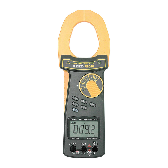
- Page 1 R5060 Model True RMS AC/DC Clamp Meter Instruction Manual reedinstruments REED Instruments 1-877-849-2127 | info@reedinstruments.com | www.reedinstruments.com...
-
Page 2: Table Of Contents
Frequency Measurement ............10 Duty Cycle Measurement ............11 Zero Adjustment ............... 11 Data Hold Operation ..............11 Relative Operation ..............11 Backight Operation ..............11 Fuse and Battery Replacement ........... 12 reedinstruments REED Instruments 1-877-849-2127 | info@reedinstruments.com | www.reedinstruments.com... -
Page 3: Safety
• Even though the ohm and capacitance ranges have an overload protection circuit, it is prohibited to apply any voltage to the input terminal when taking measurements • The water resistance casing is applicable for the front panel on the instrument only. Do not throw the instrument into water or the meter will be damaged permanently • When changing the test leads you should only use the replacements that have the approval of CAT III-1000V • Only use a dry cloth to clean the plastic case Caution: Risk of electric shock. Caution: Do not apply overload voltage or current to the input terminal. Always remove test leads before opening the battery cover. reedinstruments REED Instruments 1-877-849-2127 | info@reedinstruments.com | www.reedinstruments.com... -
Page 4: Features
Current Sensor: Hall effect sensor Zero adjustment: DC: Push button adjustment Other ranges: Automatic adjustment Over-input: Indication of “1” or “-1” Sampling Time: Approximately 0.35 seconds Operating Temp: 0°C to 50°C (32°F to 122°F) Operating Humidity: Less than 80% RH Max. Jaw Open Size: 60mm (2.36”) diameter Weight: 380g/0.85lb (including battery) Dimensions: 255 x 73 x 38mm (10 x 2.9 x 1.5”) Power Supply: One 9V battery (included) Power Consumption: Approximately DC 5mA Includes: TL-88-1 test leads, one 5 x 20mm 500mA fuse, and one 6AM6X 9V battery Optional Accessories: Carrying Case (CA-05A) Fused Test Leads (FC-300) reedinstruments REED Instruments 1-877-849-2127 | info@reedinstruments.com | www.reedinstruments.com... - Page 5 AC/DC 400V * See Notes On 500nF 100pF Following Page 0.001uF 50uF 0.01uF Frequency 0.001Hz ± (1% + 5d) AC/DC 1000V (>5V) 50Hz 0.01Hz 500Hz 0.1Hz 5KHz 50KHz 0.01KHz 100KHz 0.1KHz Duty Cycle 1% to 99% 0.10% Diode Short/non conductance, good/detect test Continuity Meter will beep if measuring resistance is less than 10 ohm reedinstruments REED Instruments 1-877-849-2127 | info@reedinstruments.com | www.reedinstruments.com...
-
Page 6: Instrument Description
• The accuracy of the capacitance ranges are after the zero adjustment (see page 11) has been executed Instrument Description 1. Clamp jaws 10. Manual range select button 2. Trigger 11. Display 3. Function indicator 12. uA/mA direct current input terminals 4. Function rotary switch 5. DC zero button 13. V, ohm, Hz, diode, 6. Relative button continuity & capacitance 7. Data hold/backlight button input terminals 8. V/Hz/% (duty cycle) button 14. Battery cover/compartment 9. Function button 15. Stand reedinstruments REED Instruments 1-877-849-2127 | info@reedinstruments.com | www.reedinstruments.com... - Page 7 Ω, KΩ, MΩ Units for resistance measurements Appears when the diode function is active Appears when measuring negative DC values Backlight is on Unit for duty cycle measurements uA, mA, A Units for current measurements Hz, KHz Units for frequency measurements nF, uF Units for capacitance measurements Appears when operating clamp-on current measurements reedinstruments REED Instruments 1-877-849-2127 | info@reedinstruments.com | www.reedinstruments.com...
-
Page 8: Operating Instructions
Ω terminal. Move the function rotary switch to the position and press the function button until the display shows . Note: A beep will sound when the resistance value is less than 10 ohm Diode Test Connect the Black test lead into the COM terminal. Connect the Red test lead into the terminal. Move the function rotary switch to the position and press the function button until the display shows a) When connected with the polarity as shown in Fig. 1, a forward current flow is established and the approximate diode forward Voltage (VF) value, in volts, will appear on the display. If the diode under test is defective a value near .000 (short circuit) or 1 (open circuit) will be displayed. reedinstruments REED Instruments 1-877-849-2127 | info@reedinstruments.com | www.reedinstruments.com... -
Page 9: Ac Current Measurement (Clamp-On)
DC Current Measurement (Clamp-on) Move the function rotary switch to the 2000A position and press the function button until the display shows . Push the DCA Zero button for at least 2 seconds to display a value of zero. Press the trigger to open the current sensor jaws and clamp it around the measuring conductor only Note: It is recommended to use the auto range mode during measurements. If you press the range button during auto range mode the meter will hold the range. For your safety please insert the terminal rubber cover (Fig. 3) for protection. Fig.3 reedinstruments REED Instruments 1-877-849-2127 | info@reedinstruments.com | www.reedinstruments.com... -
Page 10: Ac Current Measurement (Direct Input)
Frequency Measurement Connect the Black test lead into the COM terminal. Connect the Red test lead into the Hz terminal. Move the function rotary switch to the Hz position and press the Hz/% button until Hz is displayed on the screen. During a frequency measurement the meter will always perform under the auto range mode. reedinstruments REED Instruments 1-877-849-2127 | info@reedinstruments.com | www.reedinstruments.com... -
Page 11: Duty Cycle Measurement
Data Hold Operation Press the hold button and the displayed value will hold and will appear. Press the hold button again to release the data hold function. Relative Operation While taking a measurement the meter will store the last measured value. Press the relative button once and LCD will show a value of zero The newly inputted measured values will automatically be deducted from the last measured values and those new values will appear on the display. To release the relative measurement function press the relative button, and the marker will disappear. Backight Operation Push the backlight button for about two seconds for the LCD to illuminate. reedinstruments REED Instruments 1-877-849-2127 | info@reedinstruments.com | www.reedinstruments.com... -
Page 12: Fuse And Battery Replacement
Fuse and Battery Replacement Fuse Replacement 1) The meter is provided with one 5 x 20mm 500mA fuse for current (direct input) measurements and current range overload protection purposes 2) When the direct input current range isn’t operating check to see if the fuse is broken 3) To replace the fuse, open the housing case and remove the fuse from the main PC board 4) Replace the fuse according the specifications and replace the housing case Battery Replacement Caution: Remove test leads before opening the battery cover 1) When the LCD display shows you will need to replace the battery 2) Loosen the screw on the battery cover by screwdriver and remove the battery 3) Replace with 9V battery and replace the cover Notes _________________________________________ ________________________________________________ ________________________________________________ ________________________________________________ ________________________________________________ ________________________________________________ ________________________________________________ reedinstruments REED Instruments 1-877-849-2127 | info@reedinstruments.com | www.reedinstruments.com... - Page 13 Notes __________________________________________ ________________________________________________ ________________________________________________ ________________________________________________ ________________________________________________ ________________________________________________ ________________________________________________ ________________________________________________ ________________________________________________ ________________________________________________ ________________________________________________ ________________________________________________ ________________________________________________ ________________________________________________ ________________________________________________ ________________________________________________ ________________________________________________ ________________________________________________ reedinstruments REED Instruments 1-877-849-2127 | info@reedinstruments.com | www.reedinstruments.com...
- Page 14 Notes _________________________________________ ________________________________________________ ________________________________________________ ________________________________________________ ________________________________________________ ________________________________________________ ________________________________________________ ________________________________________________ ________________________________________________ ________________________________________________ ________________________________________________ ________________________________________________ ________________________________________________ ________________________________________________ ________________________________________________ ________________________________________________ ________________________________________________ ________________________________________________ reedinstruments REED Instruments 1-877-849-2127 | info@reedinstruments.com | www.reedinstruments.com...
- Page 15 Notes _________________________________________ ________________________________________________ ________________________________________________ ________________________________________________ ________________________________________________ ________________________________________________ ________________________________________________ ________________________________________________ ________________________________________________ ________________________________________________ ________________________________________________ ________________________________________________ ________________________________________________ ________________________________________________ ________________________________________________ ________________________________________________ ________________________________________________ ________________________________________________ reedinstruments REED Instruments 1-877-849-2127 | info@reedinstruments.com | www.reedinstruments.com...
- Page 16 Notes __________________________________________ ________________________________________________ ________________________________________________ ________________________________________________ ________________________________________________ ________________________________________________ ________________________________________________ ________________________________________________ ________________________________________________ ________________________________________________ ________________________________________________ ________________________________________________ ________________________________________________ ________________________________________________ ________________________________________________ ________________________________________________ For service on this or any other REED product or information on other REED products, contact REED Instruments at info@reedinstruments.com reedinstruments REED Instruments 1-877-849-2127 | info@reedinstruments.com | www.reedinstruments.com...
Need help?
Do you have a question about the R5060 and is the answer not in the manual?
Questions and answers