Table of Contents
Advertisement
Quick Links
Advertisement
Table of Contents

Related Manuals for REED R5010


Summary of Contents for REED R5010
- Page 1 Black Black R5010 Model Pantone 534 Blue - 100/80/30/5 Pantone 534 Blue - 100/80/30/5 TRMS Digital Multimeter Pantone 485 Red - 10/100/100/5 Pantone 485 Red - 10/100/100/5 Pantone 123 Yellow - 0/27/100/ Pantone 123 Yellow - 0/27/100/ Instruction Manual reedinstruments...
-
Page 2: Table Of Contents
Table of Contents Safety ..................3-4 Features ..................5 Specifications ................5-8 Instrument Description ...............8-9 Operating Instructions ............10-16 DC Voltage Measurement ............10 AV Voltage Measurement .............10-11 DC Current Measurement ............11 AC Current Measurement ............12 Resistance Measurement ............13 Continuity Check ............... 13 Diode Test ................. -
Page 3: Safety
Safety This symbol adjacent to another symbol, terminal or operating device indicates that the operator must refer to an explanation in the Instruction Manual to avoid personal injury or damage to the meter. Indicates a potentially hazardous situation, which if not WARNING avoided, could result in death or serious injury. - Page 4 Warnings This meter has been designed for safe use, but must be operated with caution. The warnings listed below must be carefully followed for safe operation. 1. NEVER apply voltage or current to the meter that exceeds the specified maximum Input Protection Limits: Function Maximum Input V DC or V AC...
-
Page 5: Features
Features • True RMS AC/DC voltage and current measurements • 0.05% basic DC accuracy • 40,000-count resolution • Measures frequency, capacitance and temperature • Diode check and continuity test • Backlit LCD readout with analog bar graph • 1000V input protection on all ranges •... - Page 6 50 to 1000Hz 400μA 0.1μA 4000μA 1μA 40mA 0.01mA ±(1.5% reading + 3 digits) 400mA 0.1mA AC Current 0.01A (20A: 30 sec max with reduced accuracy) All AC voltage ranges are specified from 5% of range to 100% of range NOTE: Accuracy is stated at 65 F to 83 F (18...
-
Page 7: Low Battery Indication
• (+ digits) – This is the accuracy of the analog to digital converter Enclosure: Double molded, waterproof Shock (Drop Test): 6.5 feet (2 meters) Diode Test: Test current of 0.9mA maximum, open circuit voltage 2.8V DC typical Continuity Check: Audible signal will sound if the resistance is less than 35Ω... -
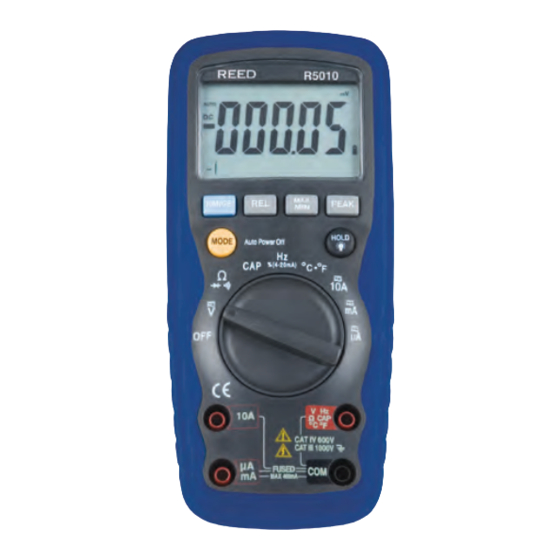
Page 8: Instrument Description
Storage Humidity: <80% Operating Altitude: 7000ft. (2000 meters) maximum Weight: 0.753lb (342g) includind holster Size : 7.36” x 3.2” x 2.0” (187 x 81 x 50mm) (includes holster) Safety: This meter is intended for origin of installation use and protected, against the users, by double insulation per EN61010-1 and IEC61010-1 2nd Edition (2001) to Category IV 600V &... - Page 9 Display Description Continuity Diode test Battery status nano (10-9) (capacitance) µ micro (10-6) (amps, cap) milli (10-3) (volts, amps) Amps kilo (103) (ohms) Farads (capacitance) mega (106) (ohms) Ω Ohms PEAK Peak Hold Hertz (frequency) Volts Percent (duty ratio) Relative Alternating current AUTO Autoranging...
-
Page 10: Operating Instructions
Operating Instructions WARNING: Risk of electrocution. High-voltage circuits, both AC and DC, are very dangerous and should be measured with great care. 1. ALWAYS turn the function switch to the OFF position when the meter is not in use 2. If “OL” appears in the display during a measurement, the value exceeds the range you have selected. -
Page 11: Dc Current Measurement
1. Set the function switch to the green VAC/Hz/% position 2. Insert the black test lead banana plug into the negative COM jack Insert red test lead banana plug into the positive V jack 3. Touch the black test probe tip to the neutral side of the circuit Touch the red test probe tip to the “hot”... -
Page 12: Ac Current Measurement
AC Current (Frequency, Duty Cycle) Measurement CAUTION: Do not make 20A current measurements for longer than 30 seconds. Exceeding 30 seconds may cause damage to the meter and/or the test leads. Insert the black test lead banana plug into the negative COM jack For current measurements up to 4000µA AC, set the function switch to the yellow µA position and insert the red test lead banana plug into the µA/mA jack... -
Page 13: Resistance Measurement
Resistance Measurement WARNING: To avoid electric shock, disconnect power to the unit under test and discharge all capacitors before taking any resistance measurements. Remove the batteries and unplug the line cords. 1. Set the function switch to the green Ω CAP position 2. -
Page 14: Temperature Measurement
Temperature Measurement 1. Set the function switch to the green Temp position 2. Insert the Temperature Probe into the input jacks, making sure to observe the correct polarity 3. Press the MODE button to indicate ºF or ºC 4. Touch the Temperature Probe head to the part whose temperature you wish to measure. -
Page 15: 4-20Ma Measurement
% 4 – 20mA Measurement 1. Set up and connect as described for DC mA measurements 2. Set the rotary function switch to the 4-20mA% position 3. The meter will display loop current as a % with 0mA=-25%, 4mA=0%, 20mA=100%, and 24mA=125% Autoranging/Manual Range Selection When the meter is first turned on, it automatically goes into AutoRanging. -
Page 16: Relative Mode
Relative Mode The relative measurement feature allows you to make measurements relative to a stored reference value. A reference voltage, current, etc. can be stored and measurements made in comparison to that value. The displayed value is the difference between the reference value and the measured value. -
Page 17: Low Battery Indication
Low Battery Indication With a fresh battery installed, the battery icon with four lines above it will be displayed in the lower right corner of the LCD. The lines will disappear as the battery is used. When the icon appears alone in the display, the battery should be replaced. -
Page 18: Battery Replacement
Battery Installation WARNING: To avoid electric shock, disconnect the test leads from any source of voltage before removing the battery cover. 1. Turn power off and disconnect the test leads from the meter 2. Open the rear battery cover by removing two screws (B) using a Phillips head screwdriver 3. -
Page 19: Replacing The Fuses
Blue - 100/80/30/5 Pantone 534 Blue Yellow - 0/27/100/0 Pantone 123 Yellow For service on this or any other REED product or information on other Red - 10/100/100/5 Pantone 485 Red Yellow - 0/27/100/0 Pantone 123 Yellow REED products, contact REED Instruments at info@reedinstruments.com. - Page 20 Notes _________________________________________ ________________________________________________ ________________________________________________ ________________________________________________ ________________________________________________ ________________________________________________ ________________________________________________ ________________________________________________ ________________________________________________ ________________________________________________ ________________________________________________ ________________________________________________ ________________________________________________ ________________________________________________ ________________________________________________ ________________________________________________ ________________________________________________ Blue - 100/80/30/5 Pantone 534 Blue Blue - 100/80/30/5 Pantone 534 Blue Yellow - 0/27/100/0 Pantone 123 Yellow Yellow - 0/27/100/0 Pantone 123 Yellow Red - 10/100/100/5 Red - 10/100/100/5 ________________________________________________...
Need help?
Do you have a question about the R5010 and is the answer not in the manual?
Questions and answers