
Related Manuals for REED R5050


Summary of Contents for REED R5050
- Page 1 Black R5050 Model Pantone 534 Blue - 100/80/30/5 TRMS AC/DC Clamp Meter Pantone 485 Red - 10/100/100/5 Pantone 123 Yellow - 0/27/100/ Instruction Manual reedinstruments 1.800.561.8187 information@itm.com www. .com...
-
Page 2: Table Of Contents
Product Maintenance ..............13 Blue - 100/80/30/5 Pantone 534 Blue Yellow - 0/27/100/0 Pantone 123 Yellow For service on this or any other REED product or information on other Red - 10/100/100/5 Pantone 485 Red Yellow - 0/27/100/0 Pantone 123 Yellow REED products, contact REED Instruments at info@reedinstruments.com. -
Page 3: Safety
When servicing this meter, use only specified replacement parts. For service Red - 10/100/100/5 Pantone 485 Red Yellow - 0/27/100/0 Pantone 123 Yellow (repairs or calibration) on this or any other REED product or information on other REED products, contact REED Instruments at info@reedinstruments.com. Blue - 100/80/30/5 Pantone 534 Blue reedinstruments Black Rich Black - 20/20/20/100 1.800.561.8187... -
Page 4: Features
Features • True RMS measurements • 3-3/4 digit LCD with high-speed, 42-segment bargraph • Max/Min and Data Hold functions • Peak Hold function • Frequency measurement • Diode and continuity test with beeper • Polarity and overload indications • Auto or manual ranging • Auto power-off • Low battery indication Specifications Digital Display: 3 3/4 digits LCD display with maximum reading 3999 Analog Display: Fast 40 segment analog bar graph display Symbol & Scale Range: Automatic display according symbols and range input signal Polarity: is displayed when negative signal applied to the input Over Load: is displayed when input signal exceeds range Sample Rate:... - Page 5 Electrical Specifications The accuracy specification is defined as ± (…% of reading+ …count) at < 23±5°C, 80%RH TRMS for ACV and ACA accuracy are specified from 5% to 100% of the range. For the accuracy add ±(1% of reading) on Crest Factor 1.4<CF<3 at full scale & CF<6 at half scale. Range Resolution Accuracy Overload Protection 0.01A 50 ~ 60Hz 60 ~ 500Hz 400A 0.1A ± (1.9% rdg + ±(2.5% rdg + 1200Arms 5 digits) 5 digits ) 1000A Range Resolution Accuracy Overload Protection 0.01A 400A 0.1A ± (2.5% reading + 10 digits) 1200Arms 1000A ACV (Autorange) Range Resolution Accuracy Overload Protection 400V 0.1V ± (1.5% reading + 5 digits)
- Page 6 (Diode) Range Test Current Open Circuit Voltage Overload Protection 1.7mA Max. 6V Max. 600Vrms Continuity Range Active Region Overload Protection <100Ω 600Vrms Frequency (Hz) (Autorange) Function Range Resolution Sensitivity Accuracy 4KHz 2Arms ±(0.1% reading + A-Hz 1 digits) (20~10KHz) 10KHz 10Hz 5Arms 4KHz 5Vrms ±(0.1% reading + V-Hz 1 digits) (10~10KHz) 10KHz 10Hz 10Vrms Blue - 100/80/30/5 Pantone 534 Blue Yellow - 0/27/100/0 Pantone 123 Yellow...
-
Page 7: Instrument Description
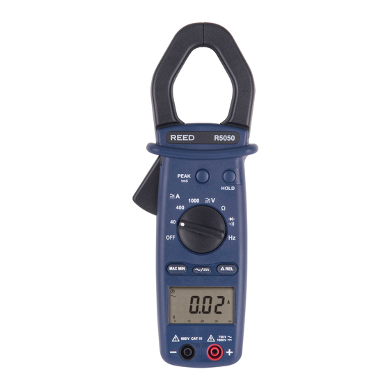
Instrument Description 1 — Current Sensing Clamp 2 — Clamp opening handle 3 — Function select dial 4 — Hold Button 5 — Peak Hold Button 6 — Maximum Minimum Button 7 — AC/DC Select Button 8 — Relative Button 9 — LCD Display 10 — “COM” Terminal 11 — “ + ” Test Terminal Display Positive Peak detect indication Relative indication Continuity with beeper Diode function indication Alternative Negative Peak detect indication Auto Power Off indication Data Hold indication Manual range indication Resistance measure- ment indication Frequency measure-... - Page 8 Data Hold Function Press the “HOLD” button at any time to hold the current reading. To release the data being held, simply press the “HOLD” button again. Peak Hold Function This meter is designed with 1ms peak hold function at ACA, ACV, DCA and DCV ranges. Before performing a peak hold operation, a calibration process must be completed first. To do this, press and hold the peak button for 2 seconds. “CAL” will dis- play on the LCD and the offset will be calculated and kept in the meter. After the calibration is complete, you can choose P+ or P- by pressing the “PEAK + HOLD” button to keep the peak reading. To return the meter back to normal operation, press the “PEAK” button for 2 seconds. When the function range changes, the meter will require another calibra- tion for peak measurement. MAX/MIN Function This meter is designed with a MAX/MIN function at ACA, ACV, DCA and DCV ranges. Press the “MAX/MIN” button once to set the meter to the MAX mode. Press it once again to set the meter to MIN mode.
-
Page 9: Measurement Procedures
Measurement Procedures Current Measurement Switch the main function selector to proper current range. Open the clamp by pressing the jaw-opening handle and insert the cable to be measured into the jaw. Choose AC current measurement by press- ing the “AC/DC” button for ACA readings. To measure DC current, choose DC measurement by pressing the “AC/DC” button. Wait for the reading to stabilize then press the “REL” button to reset the reading. Once completed, insert the cable to be measured into the jaw and read the value. Notes: Before taking this measurement, disconnect the test leads from the meter for safety. If the reading is difficult to read, push the “HOLD” button and read the result later. CORRECT INCORRECT Blue - 100/80/30/5... -
Page 10: Voltage Measurement
Voltage measurement Switch the main function selector to Voltage Range. Connect the Red test lead to the “ ” terminal and the Black one to the “COM” terminal. Choose AC or DC by pressing the AC/DC button. Measure the voltage by touching the test lead tips to the test circuit where the value of voltage is needed. Read the result on the LCD panel. Resistance measurement Ω Switch the main function to the “ ” range, verify that the power line is disconnected from the system. Connect the Red test lead to the “... -
Page 11: Continuity Test
Continuity Test Switch the main function to the “ ” range, verify Beeper that the power line is disconnected from the system. Connect the Red test lead to the “ ” terminal and the Black one to the “COM” terminal. Connect the tips of the test lead to the points where the value of the conduction condition is needed. - Page 12 Frequency measurement from the terminals Switch the main function to the “ ” range. Connect the Red test lead to the “ ” terminal and the Black one to the “COM”. Connect the tips of the test leads to the points where the frequency of the voltage signal is required. Read the value one the LCD panel. Frequency measurement with the clamp Switch the main function to the “ ” range. Open the clamp by pressing the clamp-opening handle and insert the cable to be measured into the clamp. Close the clamp and you will find the reading on the LCD panel.
-
Page 13: Battery Replacement
Blue - 100/80/30/5 Pantone 534 Blue Yellow - 0/27/100/0 Pantone 123 Yellow For service (repairs or calibration) on this or any other REED product or information on other REED products, contact REED Instruments at Red - 10/100/100/5 Pantone 485 Red Yellow - 0/27/100/0 Pantone 123 Yellow info@reedinstruments.com. - Page 14 Notes _________________________________________ ________________________________________________ ________________________________________________ ________________________________________________ ________________________________________________ ________________________________________________ ________________________________________________ ________________________________________________ ________________________________________________ ________________________________________________ ________________________________________________ ________________________________________________ ________________________________________________ ________________________________________________ ________________________________________________ ________________________________________________ ________________________________________________ Blue - 100/80/30/5 Pantone 534 Blue Yellow - 0/27/100/0 Pantone 123 Yellow ________________________________________________ Red - 10/100/100/5 Pantone 485 Red Yellow - 0/27/100/0 Pantone 123 Yellow Blue - 100/80/30/5 Pantone 534 Blue...
- Page 15 Notes _________________________________________ ________________________________________________ ________________________________________________ ________________________________________________ ________________________________________________ ________________________________________________ ________________________________________________ ________________________________________________ ________________________________________________ ________________________________________________ ________________________________________________ ________________________________________________ ________________________________________________ ________________________________________________ ________________________________________________ ________________________________________________ ________________________________________________ Blue - 100/80/30/5 Pantone 534 Blue Yellow - 0/27/100/0 Pantone 123 Yellow ________________________________________________ Red - 10/100/100/5 Pantone 485 Red Yellow - 0/27/100/0 Pantone 123 Yellow Blue - 100/80/30/5 Pantone 534 Blue...
- Page 16 Notes _________________________________________ ________________________________________________ ________________________________________________ ________________________________________________ ________________________________________________ ________________________________________________ ________________________________________________ ________________________________________________ ________________________________________________ ________________________________________________ ________________________________________________ ________________________________________________ ________________________________________________ ________________________________________________ ________________________________________________ ________________________________________________ ________________________________________________ Blue - 100/80/30/5 Pantone 534 Blue Yellow - 0/27/100/0 Pantone 123 Yellow ________________________________________________ Red - 10/100/100/5 Pantone 485 Red Yellow - 0/27/100/0 Pantone 123 Yellow Blue - 100/80/30/5 Pantone 534 Blue...
Need help?
Do you have a question about the R5050 and is the answer not in the manual?
Questions and answers