Table of Contents
Advertisement
Quick Links
Advertisement
Table of Contents

Related Manuals for Klark Teknik DN9848


Summary of Contents for Klark Teknik DN9848
- Page 1 DN9848 OPERATORS MANUAL Klark Teknik Group, Klark Teknik Building, Walter Nash Road, Kidderminster. Worcestershire. DY11 7HJ. England. Tel:+44 (0) 1562 741515 Fax:+44 (0) 1562 745371 Email: pro_audio_group@compuserve.com Website: www.klarkteknik.com...
- Page 3 BETTER BY DESIGN DESIGNED FOR APURE PERFORMANCE DECLARATION OF CONFORMITY Klark Teknik Group (UK) PLC Klark Teknik Building, Walter Nash Road, Kidderminster, Worcestershire, DY11 7HJ Declare that a sample of the following product:- Product Type Number Product Description Nominal Voltage (s)
-
Page 5: Table Of Contents
Contents Thank you for using a Klark Teknik product Page 1 Page 2 After you have unpacked Introduction Page 3 Page 5 Installation and Connection Rear panel connectors Page 6 Page 7 User interface Controls Page 8 Page 11 Main menu structure... -
Page 7: Thank You For Using A Klark Teknik Product
Thank You For Using This Klark Teknik Product To obtain maximum performance from this precision electronic product, please study these instructions carefully. Installation and operating the DN9848 is not complicated, but the flexibility provided by its operating features merits familiarisation with its controls and connections. This unit has been prepared to comply with the power supply requirements that exist in your location. -
Page 8: After You Have Unpacked
If, however, the unit shows any signs of damage, notify the transportation company without delay. Only you, the consignee, may institute a claim against the carrier for damage during transportation. If necessary, contact your supplier or as a last resort, your Klark Teknik importing agent, who will fully co-operate under such circumstances. -
Page 9: Introduction
A+B+C+D (channels summed at -6dB) Though the DN9848 utilises a fully digital processor, it maintains the operational paradigm, as well as the sonic integrity, of a high quality analogue unit. In addition to guaranteeing absolutely precise filter operation, the use of digital technology provides unrivaled flexibility of routing, the ability to program delays into both the input and output channels, extensive equalisation on both the input and output channels, and of course programmability. - Page 10 All the memory areas are monitored by an error checking system. If an error is diagnosed, the DN9848 will attempt to correct the error and also display a warning message to alert the user.
-
Page 11: Installation And Connection
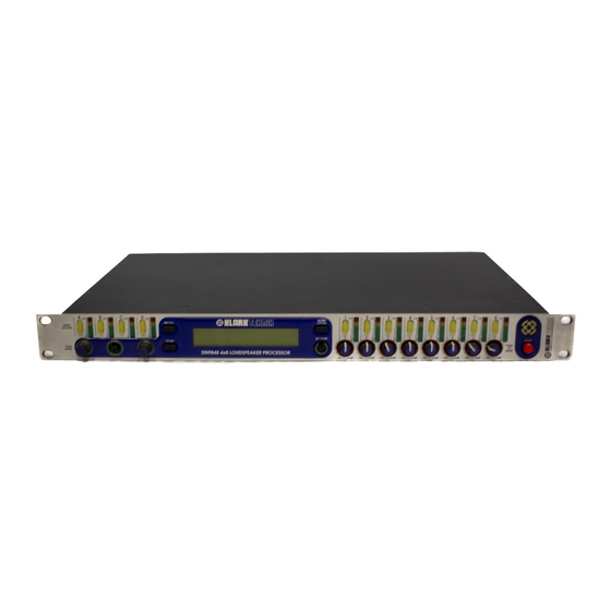
Installation The DN9848 is housed in a standard, 1U, 19" rack case.Allow adequate ventilation and avoid mounting the unit directly above power amplifiers or other devices that radiate significant amounts of heat. Where necessary, use fan cooled racks. This device must be grounded and must use an approved mains fuse. The switch mode power supply automatically adjusts itself to 50/60Hz mains supplies in the 100 to 240V (+/- 10%)AC range. -
Page 12: Rear Panel Connectors
Rear Panel Connections Both the input and output channels are accessed via electronically balanced XLR connectors wired pin 1 ground, pin 2 hot, pin 3 cold. These may be used unbalanced where necessary by connecting the ground and cold pins together, though balanced operation is recommended. -
Page 13: User Interface
User Interface The user interface has been designed to be clear and straightforward with the main functions divided into five menus covering the input channels, output channels, patch loading, patch saving and system setup. Each menu is stepped through linearly with three rotary controllers being used to edit the displayed parameters directly. -
Page 14: Controls
Controls THE INPUT CHANNELS Each input channel comprises an input gain stage followed by an eight-band, fully parametric equaliser, a full-band compressor and a delay. The input metering monitors the output from each processing stage to avoid the possibility of inadvertent clipping within the processing chain. Input block diagram: Input PEQ 5... - Page 15 INPUT BARGRAPH METERS The input 9-segment bargraph meters can display either level or compressor gain reduction. When the input signal is below the compressor threshold, the meters display the difference between the current signal level and the compressor threshold so as to show the available headroom before compression. When the signal exceeds the compressor threshold, the meters read downward from the 0 dB LED to show the amount of gain reduction taking place.
- Page 16 RS-485 for remote control. POWER The power switch activates the unit and the Klark Teknik logo on the front panel will illuminate. The circuitry is designed so that no audio transients or thumps are generated when powering up or down. It...
-
Page 17: Main Menu Structure
Main Menu Structure Main menu structure diagram:... -
Page 18: Save/Load Routine
Save/load Routine RECALLING PATCHES Pressing RECALL initiates the Recall sequence allowing the screen data entry controllers X, Y and Z to be used to select the memory bank (Preset, System and User). A message instructs that the Recall sequence can be aborted by pressing the HOME (SETUP) key, whereupon the display returns to the HOME page. -
Page 19: System Setup Menu
System Setup Menu The System Setup menu of the DN9848 enables global parameters: LCD contrast, RS-485 channel, System and Panel Lockout status, the delay time units, power-on options on and the working memory name. Note that if an RS-485 channel (other than Off) is selected, the front panel controls (other than the HOME (SETUP) button)will not function. - Page 20 Diagram Showing system setup menu screen: SETUP SETUP SETUP RS-485 Channel SETUP SETUP Front Panel SETUP Locked SETUP SETUP SETUP SETUP...
- Page 21 SECURITY A number of lockout modes have been included to prevent tampering with the unit in situations where unauthorised or unqualified personnel may have physical access. FRONT PANEL LOCKOUT This facility enables the user to set a password of up to 24 characters in order to disable the front panel controls.
- Page 22 Block diagram showing security menus: SETUP SETUP SETUP SETUP RS-485 Channel SETUP SETUP...
- Page 23 RS-485 LOCAL OVERRIDE In normal use, the RS-485 channel number is set to Off in the Setup menu. If a channel number is selected, the HOME (SETUP) key will still function but all other front panel controls (other than LCD contrast) will be inoperative (regardless of the Panel Lockout status) as the unit now expects to receive commands via the RS-485 interface.
-
Page 24: Input Menu Structure
Input Menu Structure Each of the Input channels comprises a gain control, eight fully parametric EQ stages, a compressor and a delay line, monitored by a dual function bargraph meter that shows both signal headroom and compressor gain reduction. Input channel menu block: INPUT INPUT... - Page 25 INPUT GAIN/DELAY Note that the delay units are selected in the Setup menu. Input Delay/Gain Page X: Not used Y: Input Delay Z: Input Gain. PARAMETRIC EQUALISER Each of the eight stages is identical, each being accessed via a separate menu page. Input PEQ Pages 1 - 8 X: Frequency.
-
Page 26: Output Menu Structure
The Output Menu Structure Each of the eight output channels provides configurable high and low-pass filters for setting the crossover characteristics as well as six further stages of fully parametric equalisation that may be used to compensate for system or enclosure characteristics. Delay of up to 300ms is available in addition to gain control, muting and limiting. - Page 27 ROUTING/OUTPUT DELAY Each outputs can select one of the following sources as its input: Delay Units: Time or a choice of imperial or metric distance as selected in the Setup menu. The choice of delay units applies to both the input and output channels. Routing/Output Delay Page X: Routing option.
- Page 28 The output limiter is a peak reading design, the main function of which is to protect equipment being fed from the DN9848 from being driven into clipping. In order to accomplish this, the limiter acts very quickly and employs an intelligent auto system that adjusts the 'look ahead' time according to the release time setting.
-
Page 29: Test Mode
Test Mode If the Setup key is held down while the unit is powered up, the DN9848 automatically enters its diagnostic mode, displaying a Test menu. This is for use by service personnel only. If this mode is entered inadvertently, power down the unit, then power up again normally. -
Page 30: Operational Example
Operational Example Quick Start This section assumes that the DN9848 is not locked and that the user is familiar with the concepts of crossovers, compressors, equalisers and limiters. Each input channel includes eight parametric equalisation stages, up to 1000ms of delay, gain control and compression. - Page 31 The Security features are located in the Setup menu, accessed by pressing the HOME (SETUP) key and holding it down for a minimum of 2 seconds. Even when the unit is locked, the menu pages relevant to password entry will always be accessible. There are two types of lockout: Full Panel Lock and System Lock.
-
Page 32: Technical Specification
Technical Specification Audio Inputs Four Type Electronically balanced (Pin 2 Hot) Impedance Balanced Unbalanced Common Mode Rejection >80 dB @ 1 kHz Maximum level + 21 dBu Audio Outputs Eight Type Electronically Balanced (Pin 2 Hot) Minimum load impedance 56 /20nF Source impedance Maximum level + 21 dBu into >... - Page 33 Output Processing (per channel) Routing Route from inputs: A, B, C, D, A+B, C+D, A+B+C+D None ChannelA Channel B Channel C Channel D A+B (channels summed at -3dB with balance control)) C+D (channels summed at -3dB with balance control)) A+B+C+D (channels summed at -6dB) Note that sources comprising summed channels will only be a available if the input channel delays for the summed channels...
- Page 34 Parametric EQ 1/Low shelf filter Frequency range: 20 Hz to 20 kHz in 21 steps per octave Boost/cut: +12/-12 dB in 0.1 dB steps Parametric EQ Bandwidth: 3.0 to 0.08 Shelf slope: 6 dB/Oct and 12 dB/Oct Parametric EQ 2-5 Frequency range: 20 Hz to 20 kHz in 21 steps per octave Boost/cut: +12/-12 dB in 0.1 dB steps...
Need help?
Do you have a question about the DN9848 and is the answer not in the manual?
Questions and answers