Table of Contents
Advertisement
Software Version 3.02
Telex Communications (UK) Limited,
Klark Teknik Building,
Walter Nash Road,
Kidderminster.
Worcestershire.
DY11 7HJ.
England.
Tel:+44 (0) 1562 741515
Fax:+44 (0) 1562 745371
Email: sales@ktgplc.com
Website: www.klarkteknik.com
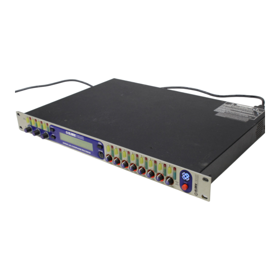
DN9848 Loudspeaker Processor Operators Manual
DOC02-DN9848 Issue 2.0 - January 2005
(c) Telex Communications (UK) Limited.
In line with the company's policy of continual improvement, specifications and function may be
subject to change without notice. This Operators Manual was correct at the time of writing. E&OE.
Advertisement
Table of Contents

Related Manuals for Klark Teknik DN9848


Summary of Contents for Klark Teknik DN9848
- Page 1 Email: sales@ktgplc.com Website: www.klarkteknik.com DN9848 Loudspeaker Processor Operators Manual DOC02-DN9848 Issue 2.0 - January 2005 (c) Telex Communications (UK) Limited. In line with the company’s policy of continual improvement, specifications and function may be subject to change without notice. This Operators Manual was correct at the time of writing. E&OE.
-
Page 3: Important Safety Instructions
IMPORTANT SAFETY INSTRUCTIONS WARNING : TO REDUCE THE RISK OF FIRE OR ELECTRIC SHOCK, DO NOT EXPOSE THIS APPLIANCE TO RAIN OR MOISTURE AVIS: RISQUE DE CHOC ELECTRIQUE. NE PAS OUVRIR These symbols are internationally accepted symbols that warn of potential hazards with electrical products. -
Page 5: Declaration Of Conformity
Details of these special measures and limitations to use are available on request and are available in product manuals. Company registration No. 2414018. A Subsidiary of Telex Communications Inc. -
Page 7: Table Of Contents
..................4 RONT ANEL ....................5 ANEL ................6 ROGRAMMING ETTINGS 4.1. The DN9848 Programming Panel .................. 6 4.2. Navigating the DN9848 Menus ..................6 4.2.1 Input and Output Menus ..................6 4.2.2 Set Up Menu ....................... 7 4.2.3 Store and Recall....................7 4.2.4... - Page 8 Power Up Options (Page 8) ..................22 ..............23 TORING AND ECALLING ETTINGS DN9848 R ...............25 EMOTE ONTROL ETUP 10. A .................27 PPLICATION OTES 10.1. The Advantage of DN9848 Look-Ahead Limiters ............27 10.2. Phase-adjustment with the DN9848 ................29 11. T .................31 ECHNICAL PECIFICATION...
-
Page 9: Attention
ATTENTION! Please ensure that you read and follow the IMPORTANT SAFETY INSTRUCTIONS at the front of this manual and the SAFETY WARNINGS and INSTALLATION CONSIDERATIONS given below. Safety Warning To prevent shock or fire hazard, do not expose the unit to rain or moisture. To avoid electrical shock do not remove covers. -
Page 11: Introducing The Dn9848
Flash memory, including up to 25 available Factory Preset cross-over set ups for commonly used Electro-Voice loudspeaker systems. Klark Teknik has a policy of continuous development and may produce updates to the DN9848 host code. These can be downloaded to the unit via the front panel PC Port. To keep up with newest... -
Page 12: Front Panel
Controls, Connectors, Indicators 2. F RONT ANEL Input channels A-D Menu Access Press to access and step through the menu pages for the Buttons A-D respective input. The available pages depend on the current security setting. The button is lit when active. Signal Level 9-segment signal meters for monitoring signal level Meters A - D... -
Page 13: Rear Panel
Controls, Connectors, Indicators 3. R ANEL IEC fused mains For mains power connection. Accepts input voltages from inlet socket 100-240V AC 50/60Hz. COMMS Communications input and output for remote control using In and Out XLR cabling. Outputs 1-8 Electronically balanced XLR audio output plugs Pinouts: Pin 1 Screen Pin 2 Hot... -
Page 14: Rogramming Ettings
4.2. Navigating the DN9848 Menus The DN9848 menu system is divided logically into Input, Output and Set Up menus, plus two function specific menus for quick access to the Store and Recall commands. A menu map is provided at the end of this section for reference purposes. -
Page 15: Set Up Menu
DN9848 Menu System If you prefer to program each parameter in turn across all the input/output channels, you can also skip across from the current channel to the same page on another input/output channel by pressing the MENU ACCESS button of the other channel. If you want to jump to the first page of a different channel, press the HOME button and then the required channel button. - Page 16 DN9848 Menu Map...
-
Page 17: Input Channels
HANNELS 5.1. Brief Technical Overview Referring to the illustration below, each input channel of the DN9848 processes the audio signal through delay and gain stages, followed by 12 bands of parametric equalisation, and a full-band compressor. All key stages are monitored for signal clipping which, if detected, lights the top red segment at the top of the input signal meter;... -
Page 18: Gain And Delay
‘below’ –40dB. Setting the gain to OFF will mute the input signal. 5.2.4 Parametric Equalisation (Pages 2 to 13) The DN9848 provides 12 parametric equalisation stages on each input channel, for equalising the input signal in respect of room/venue characteristics. Each stage can be used across the full range from 20Hz to 20kHz and is set independently via its own menu page. -
Page 19: Compression
Input Channels 5.2.5 Compression (Page 14) Each input has an independent full-range compressor to improve the dynamics of the incoming signal levels. The compressors are variable ratio and can be set to a hard knee characteristic for a sharp gain reduction response at the compression threshold, or soft knee for a more ‘musical’... -
Page 20: Output Channels
Output Channels 6. O UTPUT HANNELS 6.1. Brief Technical Overview The output channels are slightly more complex than the input channels in that they are responsible for the signal routing as well as output signal processing. At the input of each output channel is a routing block that can source the output signal from a single input, a pair of inputs, or all four inputs. -
Page 21: Setting Output Parameters
Routing (Page 2) Each output of the DN9848 can be acquired from a single input, a pair of outputs or all outputs. For paired outputs, the source inputs are attenuated by 6dB prior to summing and the ratio of the two signals used is adjustable. -
Page 22: Signal Invert, Delay And Output Level
6.2.5 Phase Adjustment (Pages 4 and 5) To meet the demands of a wide range of situations, the Klark Teknik DN9848 provides two all-pass filters with complementary control parameters for fine-tuning the phase response on each output, e.g. for alignment at cross-over. The first filter is presented as a “phase shifter” for which you can set a specific phase shift at a reference frequency, eg. -
Page 23: High Pass And Low Pass Filters (Pages 6 And 7)
6.2.6 High Pass and Low Pass Filters (Pages 6 and 7) The DN9848 provides the following high and low pass filter (HPF and LPF) options for cross-over purposes: Butterworth 6, 12, 18, 24, 36 and 48dB / Octave... -
Page 24: Parametric Equalisation (Pages 2 To 13)
Output Channels 6.2.7 Parametric Equalisation (Pages 2 to 13) The DN9848 provides six parametric equalisation Any PEQ can be used as the stages on each output channel, for equalising the reference frequency for the Phase output signal in respect of loudspeaker and/or system Shifter (see Section 6.2.5) -
Page 25: Output Limiter
Notably, the DN9848 uses a special ‘look-ahead’ limiter so that it can anticipate transient overshoots and act ‘immediately’ (see Application Notes for further details). The limiter threshold can be adjusted to accommodate the varying requirements of commercial equipment. -
Page 26: Output Gain And Mute - Front Panel Control
Output Channels The meter uses a downward relative scale where the 0 segment represents the limiter threshold. For example, if the limiter threshold is set to +5dB in the output menu page, then the signal meter 0 segment represents 5dBu true value, the –3 segment becomes 2dBu down, - 6 becomes -1dBu down and so on. -
Page 27: Dn9848 Set U P Options
Security and other Set Up Options 7. DN9848 S PTIONS 7.1. General The DN9848 provides various set up options for adapting the operation of the unit to best suit your operational requirements and preferences, as follows: Comms channel setting for remote control Security features... -
Page 28: System Protect
If correct, the display will report ‘UNLOCKED’. Press HOME to exit the page and return to normal operation. If you have entered the wrong password, the DN9848 will flag it as incorrect and return to the Panel Unlock page for a further attempt. -
Page 29: Lcd Lighting
Turn the right-hand knob clockwise to apply the password. If you have entered the wrong password, the DN9848 will flag it as incorrect and return to the Panel Unlock page for a further attempt. -
Page 30: Delay Options
For Metric or Imperial distance measurement, specify the ambient temperature of the venue using the centre knob. The DN9848 will use this to adjust the speed of sound (which varies with temperature) in the delay calculation so that accurate delays are applied to the channels. -
Page 31: Storing And Recalling Settings
Press STORE to confirm the action and return to the DN9848 Home page. The DN9848 automatically checks the memory settings and displays a warning if any errors are found. Where possible, it will also attempt to automatically correct the error. - Page 32 Press the black RECALL button to access the Recall menu. Select a User, System or Preset memory using the left, centre or right-hand knob. Press RECALL to confirm the action and return to the DN9848 Home page. The selected memory settings are recalled to the working memory.
-
Page 33: Dn9848 Remote Control Setup
ONTROL ETUP Up to 32 DN9848 Loudspeaker processors can be linked together in a daisy-chain RS-485 network for remote control from a computer running the commercially available Stardraw or Smaart software. Further details of these applications are available from the Klark Teknik website at www.klarkteknik.com... - Page 34 Remote Control Setup DN9848 Connection Laptop/PC Cable /Converter Required Connection RS-232 input to front panel D9 COM port Host cable PC PORT for short cable run USB port KK systems USB/232 converter plus host cable RS-485 input to rear panel D9 COM port RS-232/485 converter, e.g.
-
Page 35: Application Notes
All other settings are default on both units. As with all units that use sigma-delta ADC and DAC converters, there is a propagation delay from input to output, 3.2 ms for the DN9848 and 2.1 ms for the competitor unit, the additional delay in... -
Page 36: Application Notes
In order to prevent driver failure, the competitor product’s limiter threshold needs to be reduced such that the peak of the transient is at the same level as the threshold of the DN9848’s look-ahead limiter, with a major effect on efficiency of speaker systems, as the effect of reducing the limiter threshold is to limit the amount of continuous output power available, which means more amplifiers and more speaker cabinets to achieve the same SPL. -
Page 37: Phase-Adjustment With The Dn9848
The DN9848 filters provide straightforward tuning control in all cases. The first filter of the DN9848 is presented as a “phase shifter” for which you can specify a particular phase shift at a reference frequency, namely a HPF or LPF (typically the cross-over point) or one of the 6 PEQs. - Page 38 Application Notes Audio Precision 1st order allpass @ 300, 1K, 10K 01/19/01 16:00:02 +150 +150 +100 +100 -100 -100 -150 -150 C olor Lin e Style Th ick D ata Axis Gree n Solid An lr.Pha s e Left Ye llo w Solid An lr.Pha s e R igh t...
-
Page 39: Technical Specification
Technical Specification 11. T ECHNICAL PECIFICATION Audio Inputs (four) Type Electronically balanced (Pin 2 Hot) Impedance (Ω) Balanced 20k, Unbalanced 10k Common Mode Rejection >80dB @ 1kHz Maximum level + 21dBu Audio Outputs (eight) Type Electronically Balanced (Pin 2 Hot) Minimum load impedance 56Ω... -
Page 40: Technical Specification
Technical Specification High pass filter Types available Butterworth (6dB/Oct, 12dB/Oct, 18dB/Oct, 24dB/Oct, 36dB/Oct, 48dB/Oct) Linkwitz-Riley (12dB/Oct, 24dB/Oct) Bessel (12dB/Oct, 18dB/Oct, 24dB/Oct, 36dB/Oct, 48dB/Oct) 12dB/Oct Peaking 24dB/Oct Peaking Freq. Range: 20Hz to 15kHz in 21 steps/octave Peaking Filter Boost: 0dB to +6dB in 0.1dB steps. Low pass filter Types available Butterworth (6dB/Oct, 12dB/Oct, 18dB/Oct, 24dB/Oct, 36dB/Oct, 48dB/Oct) - Page 41 Technical Specification Factory Presets for X-Array Series Memory Identification P01 XW15 – 4MIX R1-3 4 x EV XW15 15” Bi-amped (8 outputs used) P02 XN/XB/2XF R2- Xn LF Xn MB Xn HF Xb LF Xf MB Xf HF Xf MF Xf HF 1 x EV XN + EV XB + 2 x EV XF (8 outputs used)
- Page 42 Technical Specification Factory Presets for X-Array Install (Xi) Series Memory Identification P08 XI1122/85 4MIX R1-2 4 x EV XI1122/85 12” Bi- amped (8 outputs used) P09 XI1122/85 & 1191 1191 SUB 1122 LF 1122 HF FULL R1-2 1191 SUB 1122 LF 1122 HF FULL 2 x EV XI1122/85 12”...
- Page 43 Technical Specification Memory Identification XI2153/64 R1-2 FULL 2 x EV XI2153/64 15” FULL Tri-amped (6 ouputs used) XI2153/64 & 1191 1191 2153 LF 2153 2153 R1-2 2 x EV XI2153/64 15” 1191 2153 LF 2153 2153 plus EV 1191 Sub Quad-amped (8 outputs used) XI1123/106 R1-2...
Need help?
Do you have a question about the DN9848 and is the answer not in the manual?
Questions and answers