
Subscribe to Our Youtube Channel
Related Manuals for Pfaff performance 2054


Summary of Contents for Pfaff performance 2054
- Page 1 PFAFF performance 2054 german engineering Service Manual and Test program 2nd edition May 2003...
-
Page 3: Table Of Contents
Page Contents Foreword Notes on the sewing machine Specifications Dismantling the housing Feeding System 1. Adjustment of the flat-toothed belt tension 2. Adjustment of feed dog in sideways direction 3. Timing of feed motion 4. Adjustment of feed dog height 5. - Page 4 43. Upgrade from a PC via a serial interface on the machine 44. Calibrating the Touch panel 45. Calibrating the knee lift potentiometer Important special functions of the performance 2054 46. Display contrast 47. Version number and status 48. Programmed patterns 49.
-
Page 5: Foreword
Foreword This service and repair manual is intended to assist you in carrying out all repairs to the machines quickly and correctly. Adjustments should only be carried out if you find the actual settings deviating from the requirements described here. When checking or adjusting a machine, please always proceed in the sequence specified. -
Page 6: Notes On The Sewing Machine
6. To avoid the risk of electric shock, do not open the machine. There are no parts inside the machine which the user can repair. This is solely the responsibility of our qualified service staff. 7. Be sure to use only original PFAFF parts. -
Page 7: Specifications
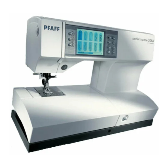
Specifications of the PFAFF performance 2054 • Electronic free-arm, utility and fancy stitch sewing machine • 1/4 VGA - touchscreen black-white graphic - display with 2 additional grey shades • 16 bit processor with 8 Kbyte RAM and 1Mbyte Flash-memory, 512 Kbyte PEROM •... - Page 8 Medium ball point Suffix = SUK Large ball point Suffix = SKF Pointed cloth point Suffix = J Leather point right hand Suffix = LR Specifications of drive motor for the PFAFF performance 2054 ____________________________________________________________________ No. 93-330 111-91/000 24 V = 8000 r.p.m.
- Page 9 Warning! It is of utmost importance to be careful to protect parts from electrostatic discharge (ESD). To prevent this from happening, circuit boards must be handled in a controlled way. Always use strap 412 23 02-01 for maintenance work.
-
Page 10: Dismantling The Housing
Dismantling the housing cover Note: Before adjusting or repairing the machine, make sure dismantle the housing covers according to the adjustment and repair instructions. • Pull out the mains plug and the socket on the machine. • Remove the needle and the presser foot shoe. •... - Page 11 • Loosen the torx screw on the face plate. • Remove the complete face plate together with the sewing lamp and cable (fig. 3). • Remove the carrying handle. • Unscrew and remove the three fastening screws on the baseplate. •...
- Page 12 • Unscrew and remove both fastening screws 7 on the free-arm cover (fig. 5). • Put the feed drop mechanism in its normal working position. • Using a small screwdriver, disengage both feed regulators 8. • Open the cable clip. •...
- Page 13 • Remove the needle plate. • Unscrew and remove both fastening screws 10 (fig. 7). • Remove the free-arm cover. • Loosen screw 11 on the stand cover (fig. 8). • Remove the stand cover.
- Page 14 • Remove fastening screw 12 and 13 on the rear housing shell (fig. 9 and 10). • Open the catch connections on the inside of the arm by pressing with your thumb against the points indicated by the arrows (fig. 11). •...
- Page 15 • Remove the connecting plug 14 from presser bar lifter sensor (fig. 12). • Remove the connecting plug 15 from button hole sensor. • Remove the connecting plug 16 from ZZ stepping motor. • Remove the connecting plug 17 from feeding stepping motor. •...
- Page 16 • Loosen fastening screws 23, 24 and 25 (fig. 13) as well as fastening screw 26 (fig. 14). • Remove the front housing shell carefully.
-
Page 17: Feeding System
Feeding system 1. Adjustment of the flat-toothed belt tension Requirement: The flat-toothed belt must be so taut that the sewing hook has no play in its rotating direction, but it must be possible to turn the machine easily. Adjustment: • Loosen screw 1 (fig. -
Page 18: Adjustment Of Feed Dog In Sideways Direction
2. Adjustment of feed dog in sideways direction Requirement: The distance of the feed dog to the right and left edges of the feed slot must be equal (fig. 2). Check: • Carry out a visual check of the feed dog position. Adjustment: •... -
Page 20: Timing Of Feed Motion
3. Timing of feed motion Operating sequence: When the rising needle has left the fabric, the feed dog moves up above the needle plate. The risen feed dog pushes the fabric to the rear. Shortly before the end of the feeding motion, the take-up lever is in its highest position (t.d.c). -
Page 22: Adjustment Of Feed Dog Height
4. Adjustment of feed dog height Requirement: In the highest position of the feed dog, the points of its teeth must protrude above the needle plate surface by 0.85 - 0.9 mm. The tolerance must not remain under or exceed 0.85 to 0.9 mm (fig. 9). Check: •... -
Page 24: Adjustment Of Synchronizer
5. Adjustment of synchronizer Note: The following machine positions or functions are controlled by the synchronizer: 1. Change of feeding direction and change of stitch length 2. Sideways movement of needle bar 3. Take-up lever top position/needle „up“ position 4. Needle „down“ position This adjustment must only be carried out when compelling reasons exist! It must be performed with absolute accuracy. -
Page 26: Adjustment Of Presser Foot Height
6. Adjustment of presser foot height Requirement: With the presser bar lifter raised there must be a clearance of 8 mm between the needle plate and the sole of the zigzag foot. Check: • Raise the presser bar lifter. • Fit the zigzag foot. -
Page 27: Adjustment Of Top Feed Foot In Sewing Direction
7. Adjustment of top feed foot in sewing direction Requirement: The front edge of the top feed foot must be between the first and second tooth point of the center tooth row of the feed dog (fig. 18). Check: • Raise the presser bar lifter. -
Page 28: Adjustment Of Top Feed Height
8. Adjustment of top feed height Requirement: In its highest working position the top feed foot must be 2 mm higher than the lower edge of the zigzag foot sole. Note: This adjustment must only be carried out when the height of the presser bar is set correctly. Check: •... -
Page 30: Adjustment Of The Height Of The Free Motion Foot
9. Adjustment of the height of the free motion foot Note: This adjustment can only be carried out when the machine is completely assembled. Requirement: When in free motion position, the standard presser foot must have a clearance of 5.0 mm to the needle plate surface (fig. -
Page 32: Zigzag Mechanism
Zigzag mechanism 10. Adjustment of needle in needle hole Requirement: At the straight stitch setting, the needle must be in the center of the needle hole (fig. 24). The widest zigzag stitches must have the same distance from the left and right needle hole edges (fig. 25). Check: •... -
Page 34: Stitch Forming Parts (Hook)
Stitch forming parts (Hook) Foreword: The sewing hook adjustment consists basically of the three following adjustments: Needle rise Needle bar height Hook-to-needle clearance Needle rise: The needle rise is the movement by which the needle must rise from its lowest position until a thread loop has formed on the side of the needle on which the scarf is located. -
Page 35: Position Of Needle In Needle Hole In Sewing Direction
11. Position of needle in needle hole in sewing direction Requirement: There must be a clearance of 0.2 mm between the back edge of the needle shank and the back edge of the needle hole in the needle plate (fig. 27). Note: Since system 130/705 H needles increase in size at the needle front side only, the point of an Nm 100 needle is positioned exactly in the middle of the needle hole (as seen in feeding direction), while the point... - Page 36 Adjustment in relation to the presser foot: • Loosen screw 52 (fig. 28). • Move pin 53 together with collar and needle frame 54 to the front or the rear until the needle is exactly in the middle of the needle hole on the presser foot. •...
- Page 37 Adjusting the needle plate: • Turn the handwheel and bring the needle to its highest position. • Remove the zigzag foot. • Turn the handwheel and bring the needle to its lowest position. • Turn adjustment eccentric 55 until the distance from the front and rear edges of the needle hole is equal (fig.
-
Page 38: Adjustment Of Hook-To-Needle Clearance
12. Adjustment of hook-to-needle clearance Requirement: At the straight stitch setting the distance of the sewing hook point from the bottom of the scarf in the needle must be 0.05 mm (fig. 31). In the widest zigzag stitch, the sewing hook point must almost touch the needle. Check: •... -
Page 39: Adjustment Of Bevel Gears
13. Adjustment of bevel gears Requirement: The bevel gears must move freely and without play. Adjustment: • Push the bevel gear with the lifting eccentric to the left until it is in contact with bevel gear 59 and has no play (fig. 32). •... -
Page 40: Sewing Hook Timing
14. Sewing hook timing Requirement: When the needle bar has moved 2.2 mm upwards from its lowest position (with the machine set for straight stitch and center needle position), the sewing hook point must be exactly opposite the center line of the needle (fig. -
Page 42: Adjustment Of Needle Bar Height
15. Adjustment of needle bar height This machine has a transverse double-rotating hook. On the right zigzag penetration, the sewing hook reaches the needle a little earlier and at the left penetration a little later than at the center penetration. Thus the looper point is positioned slightly higher above the needle-eye for the right zigzag penetration than for the left zigzag penetration (fig. -
Page 43: Adjustment The Bobbin Case Position Finger
16. Adjustment of bobbin case position finger Requirement: The clearance between the position finger and the bottom of the groove in the bobbin case base must be 0.7 mm (fig. 39). Check: • It must be possible to insert the clearance gauge (61-111 621-15) with ease but without play between the position finger and the bottom of the groove in the bobbin case base. -
Page 44: Stitching Off
Stitching off 17. Adjustment of needle threader Requirement: With the threader key pushed fully down, prong 66 must pass through in the center between the top and bottom edge of the needle eye of a needle size Nm 70 (fig. 40). Check: •... -
Page 46: Adjustment Of Bobbin Winder Stop
18. Adjustment of bobbin winder stop Requirement: The bobbin winder must stop when the thread has reached a level of 1 mm below the bobbin rim. Check: • Wind a bobbin and check that the winder stops as required. Adjustment: •... -
Page 47: Adjustment Of Bobbin Thread Tension
19. Adjustment of bobbin thread tension Requirement: The force required for pulling cotton thread 50/2 or synthetic fiber thread 100/3 off the bobbin must be approximately 25 - 30 g. Check: • When a threaded bobbin case hangs on its thread, it must not slide downwards by its own weight. •... -
Page 48: Adjustment Of Needle Thread Tension
20. Adjustment of needle thread tension Requirement: Within the adjusting range from 3 to 5, the interlacing of the needle thread and the bobbin thread (cotton thread 50/2 or synthetic fiber thread 100/3) must take place approximately in the middle of the fabric in straight and zigzag stitch setting (fig. -
Page 50: Adjustment Of Thread Check Spring Stroke
21. Adjustment of thread check spring stroke Note: The tread check spring prevents the descending needle from piercing the slack needle thread. The needle thread is slackened by the descending take-up lever. Requirement: Thread check spring 75 must keep the needle thread taut at least until the needle point enters the fabric (Fig. -
Page 52: Adjustment Of Equal Forward And Reverse Stitch Length
22. Adjustment of equal forward and reverse stitch length (for all forward and reverse controlled stitch patterns) Requirement: The darning program must be sewn as an exact rectangle (fig. 51) and not as a rhombus (fig. 52 and 53). The buttonhole bartack must cover the beginning of the right buttonhole seam (fig. 54). For this purpose the machine must be at operating temperature after 10 to 15 minutes turn-on time. -
Page 54: Making Up A Sewing Sample
This sewing sample should contain the most important stitch patterns, which can be sewn on a repaired machine (fig. 56). If the customer has special requirements, these should appear on a separate sewing sample. The following is a sewing sample from the PFAFF performance 2054 Stitch program Stitch width Stitch length Presser foot no. -
Page 55: Repair Instructions
Repair Instructions 24. Dismantling and assembling the needle thread tension Removal: • Remove the needle thread tension. • Press the two plastic noses 78 together and remove tension dial 79 (fig. 57). • Remove spring disc 80. • Turn milled nut 81 out of guide 82. •... -
Page 56: Changing The Torsion Spring In Handwheel
25. Changing the torsion spring in handwheel Dismantling the handwheel • Remove stand cover in accordance with the instructions for dismantling the housing. • Turn the handwheel until the handwheel cutout is facing upward (fig. 58). • Push lug 89 to the rear using a screwdriver. •... -
Page 58: Dismantling And Assembling Sewing Hook
26. Dismantling and assembling the sewing hook Removal: • Remove the needle. • Unscrew the presser foot. • Remove the bobbin case. • Unscrew the bobbin case position finger. • Take out the three screws with springs from behind (fig. 60). •... -
Page 60: Changing The Flat-Toothed Belt
28. Changing the flat-toothed belt Removal: • Remove the housing in accordance with the adjustment and repair instructions. • Turn the handwheel until the lobe of feed eccentric 5 is positioned at the rear (fig. 66). • Loosen fastening screw of tensioning roller. •... - Page 62 Fitting: • Lift complete hook driving shaft 28 out of the lower right calotte bearing 103 as far as it will go (fig. 66). • Pull the flat toothed belt between calotte 104 and calotte bearing 103. • Place hook driving shaft 28 exactly together with calotte 104 in the lower right calotte bearing 103. •...
- Page 64 Adjusting the machine: • Tilt the machine towards the rear. • Disconnect spring 3 (fig. 69). • Unscrew and remove screw 4. • Turn the handwheel until the lobe of feed eccentric 5 is at the rear. • Fold feed regulator 6 downward and remove it with link 7 to the left from feed bar pin. •...
- Page 65 • Fold the baseplate towards the machine. • Attach the cable clip. • Fasten the baseplate on the housing with the three fastening screws. • Attach the face plate. • Attach connection plugs 2 and 3 onto the circuit board of the front housing shell. •...
-
Page 66: Changing The Bevel Gears
29. Changing the bevel gears Note: Always change bevel gears in pairs. Removal: • Remove the mains plug of the machine. • Remove the detachable work support. • Unscrew and remove the three fastening screws of the baseplate. • Remove the three connection plugs 4, 5 and 6 from the circuit board. •... - Page 68 Fitting: • Insert the new hook driving shaft with bevel gear 59 in the sewing hook bearing (fig. 71). • Mount sewing hook 56 with the plastic disk on the sewing hook bearing and set it. • Fasten the sewing hook bearing using both screws 121 (fig. 70). Note that the sewing hook bearing is fastened parallel to the housing.
- Page 69 Now the following adjustments are to be carried out: • Section 3: Timing of the feed motion • Section 4: Adjustment of feed dog height • Section 5: Adjustment of synchronizer • Section 12: Adjustment of hook-to-needle clearance • Section 14: Hook timing •...
-
Page 70: Changing The Base Circuit Board
30. Changing the base circuit board Note: The base circuit board is only exchanged as a complete unit. Removal: • Remove the mains lead from the mains socket and from the machine. • Remove the detachable work support. • Unscrew and remove the three fastening screws on the base plate. •... - Page 71 Notes...
-
Page 72: Changing The Upper Circuit Board
31. Changing the upper circuit board Removal: • Pull out the mains plug and the socket on the machine. • Remove the needle and the presser foot shoe. • Remove the detachable work support. • Remove the top cover. • Unscrew and remove the two torx screws of the housing insert. - Page 73 Fitting: • Place the circuit board on the front housing panel. • Secure the circuit board with screws 123, 124 and 125 (fig. 74). • Mount connection plugs 2, 3, 9, 14, 15, 16, 17, 18, 19, 20, 21, 22, and 122 onto the circuit board. •...
-
Page 74: Changing The Keypad
32. Changing the keypad Removal: • Remove the mains lead from the mains socket and from the machine. • Remove the detachable work support. • Remove the folding cover. • Unscrew and remove both torx screws of the housing insert. •... - Page 75 Fitting: • Mount the keypad onto the circuit board whilst making sure that the lugs 126 and 127 lock in completely behind the circuit board (fig. 76). • Mount the facing panel onto the front housing panel and make sure that both lugs 1 lock fully into place (fig.
-
Page 76: Changing The Synchronizer Circuit Board
33. Changing the synchronizer circuit board Removal: • Remove the mains lead from the mains socket and from the machine. • Remove the detachable work support. • Remove the folding cover. • Unscrew and remove both torx screws of the housing insert. •... -
Page 78: Changing The Motor
34. Changing the motor Note: The motor is only exchanged complete. Removal: • Remove the mains lead from the mains socket and the machine. • Clap the carrying handle up. • Loosen fastening screw 11 on the stand cover (fig. 81). •... -
Page 80: Changing The Cable In The Foot Control
35. Changing the cable in the foot control Removal: • Lift rubber strip 129 and pull it out with its three feet (fig. 84). • Pull out the two plugs 130. • Unscrew and remove the four Philips screws 131. •... -
Page 82: Changing The Upper Stepping Motor
36. Changing the upper stepping motor Note: The stepping motor for sideways needle bar movement must be replaced as a complete unit. Removal: • Remove machine’s mains plug. • Remove detachable work support. • Remove the housing covers as described in this manual. •... -
Page 84: Changing The Lower Stepping Motor
37. Changing the lower stepping motor Note: The feed stepping motor is only exchanged complete. Removal: • Remove the machine’s power plug. • Remove the detachable work support. • Remove the housing according to the service manual. • Remove tension spring 3 (fig. 88). •... -
Page 86: Changing The Sd Motor Unit
38. Changing the SD motor unit Removing: • Remove the machine’s plug from the mains. • Take off the needle and the presser foot shoe. • Take off the detachable work support. • Take off the folding cover. • Release the screw on the top cover. •... - Page 87 • Pull the plug 21 from the circuit board (fig. 91). • Loosen screw 25 (fig. 92). • Press the rear housing shell back until the rearmost screw 143 is visible. • Remove the two screws 143. • Disengage the carrying handle 142. •...
- Page 88 • Release locking nut 48 (fig. 94). • Remove the threaded piece 49 from the bracket 147. • Take off the lock washer 148. • Take the toothed rocker 149 with magnet off the pin. • Take the Bowden cable out of toothed rocker 149 and bracket 147. •...
-
Page 90: Ajusting The Toothed Rocker
39. Adjusting the toothed rocker Note: Only perform this adjustment if absolutely essential. Principle: In the „sewing position“, there must be 0.5 - 0.8 mm clearance between the toothed rocker 149 and the bracket 147 (Fig. 96). Check: • Plug the machine’s mains plug into the mains. •... - Page 92 • Engage the Bowden cable at the presser bar guide. • Position the Bowden cable’s clamping plate and secure with screw 146 (fig. 97). • Insert the carrying handle 142 in the bracket (fig. 98). • Fit the complete bracket. •...
-
Page 94: Changing The Buttonhole Sensor
40. Changing the buttonhole sensor Note: The buttonhole sensor must be replaced as a complete unit. Removal: • Disconnect the machine lead cord. • Remove the needle and the presser foot. • Remove the detachable work support. • Remove the housing covers as described in this manual. •... -
Page 96: Changing The Thread Monitor With Free-Arm Cover
41. Changing the thread monitor with free-arm cover Note: The thread monitor is only exchanged complete with the free-arm cover. Removal: • Remove the machine’s mains lead. • Remove the needle and presser foot. • Remove the folding cover. • Unscrew and remove both torx screws of the housing insert. -
Page 98: Changing The Needle Threader
42. Changing the needle threader Note: The needle threader is only exchanged complete with the threader bar frame. Removal: • Remove the machine’s mains lead. • Remove the needle and the presser foot. • Press threader key 67 down completely and keep it pressed (fig. 106). •... -
Page 99: Upgrade Of The Performance 2054
Upgrade of the performance 2054 The performance 2054 is preset by the manufacturer to the language of the country in which it is sold. The customer can easily set a different language. The machine can likewise always be updated to the latest software status. -
Page 100: Calibrating The Touch Panel
44. Calibrating the Touch panel Note: The Touch panel is correctly calibrated by the manufacturer and needs only to be recalibrated if absolutely essential. Adjustment: • Press the „More options“ button simultaneously and hold them pressed. • Switch on the machine. •... -
Page 101: Important Special Functions Of The Performance 2054
Important special functions of the performance 2054 46. Display’s contrast setting Note: The Display contrast is correctly adjusted by the manufacturer and needs only to be recalibrated if absolutely essential. Basic adjustment: If the „Info“ button is pressed when the machine is switched on, the contrast adjustment menu is opened. -
Page 102: Programmed Patterns
48. Programmed patterns This is a selection of special patterns for purposes of adjusting the sewing machine. 49. Options for messages • Switch on the machine. • Touch the „Info“ button until the „Context menu“ appears. • Touch the „Options for messages“ button. •... -
Page 103: Test Program
52. Test program The following accessories must be available for conducting the test: Foot control, buttonhole guide, full bobbin case, knee lift. If a machine check is not possible, the operator is requested to perform a visual check. The message visual check and the following text are displayed: = button „+“... -
Page 104: Buttons
54. Buttons The machine buttons are represented on the screen. They are bright at the start of the test and are shown as black when the buttons (not the push-buttons) are pressed. The operator is requested to operate the buttons in any chosen order. Don’t press the buttons simultaneously. -
Page 105: Foot Control
57. Foot control The foot control is a variable resistor whose value is measured by an analogue method. When not in use, its value is „infinite“. If the foot control is being pressed, the operator is requested to release it. Press the push-button „Start“. -
Page 106: Buttonhole Control
Presser foot lift The machine moves to the corresponding positions when the appropriate buttons are pressed: • Raised position [8 mm above needle plate] The limit switch must be reached. • Middle position [5.3 mm above needle plate] • Lowered position [Foot resting on needle plate] •... -
Page 107: Synchronizer
60. Synchronizer The synchronizer consists of two forked light barriers, which scan two coded discs supplying four different signals per revolution of the machine: The handwheel must be turned twice by the operator manually, with a connected sewing mechanism. All possible combinations of the synchronizer sensor must be covered during the process. The revolutions counter is reduced in the display. -
Page 108: Machine Motor
61. Machine motor If the foot control has already been operated, the operator will be requested to release it again. The speed indicator consists of a forked light barrier, which scans a toothed wheel located on the motor shaft. The flanks of this signal are measured as a function of time and counted. The actual speed and the target speed are displayed in the form of numbers. -
Page 109: Overload Protection
63. Overload protection After pressing the foot control a further time, the overload protection is tested: The operator is requested to block the handwheel manually for about 10 seconds; this causes the machine motor to shut down for about 4 seconds. Important: The operator is only requested to release the foot control after these 4 seconds. - Page 110 PFAFF GmbH Amalienbadstraße 36 76227 Karlsruhe Printed in Germany D-Telefon + 49 (0)721/4001-0 Technische Änderungen vorbehalten Telefax + 49 (0)721/4001-513 Subject to alterations in design E-Mail: info@pfaff.com Sous toute réserve de modifications http://www.pfaff.de techniques Druckerei Gablenz GmbH Salvo modificaciones técniche Stettiner Straße 17...
Need help?
Do you have a question about the performance 2054 and is the answer not in the manual?
Questions and answers