Advertisement
Quick Links
Advertisement

Related Manuals for BW SENSING BWM427


Summary of Contents for BW SENSING BWM427
- Page 1 BWM427 Serials Modbus Dual-Axis Inclinometer Technical Manual...
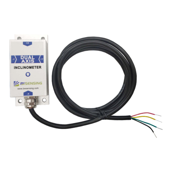
- Page 2 Modbus Dual-Axis Inclinometer Introduction Designed by BWSENSING, BWM427 is a cost-effective dual-axis inclinometer with MEMS technology and digital output. It has a measuring range of ± 90° and a full-scale accuracy of 0.01° and a operating temperature of -40℃~+85℃. The product uses a high-accuracy MEMS accelerometer and a high-resolution differential digital-to-analog converter with built-in automatic compensation and filtering algorithms to reduce errors caused by environmental changes.
-
Page 3: Specifications
Electrical Specifications Conditions Units Typical Parameters Power supply(DC) Operating current Non-loaded ℃ Operating temperature +100 ℃ Store temperature Performance Specifications Units Conditions BWM427-90 Parameters ° ±90 Measuring range Measuring axis ° 0.01 Indoor Accuracy ° Resolution 0.001 Zero temperature -40~+85℃ ±0.005 °/℃... - Page 4 BWM 427 Modbus Dual-Axis Inclinometer Mechanical Characteristic Metal connector(standard cable is 1.5m) Connector Protection level IP67 Shell material Magnesium alloy anodizing Installation Four M4 screws Package size Product Size: L90*W40.5*H26(mm) 4.5 通孔 Bare plate product size Product size: L47*W36*H15(mm) Note: ±1mm error for length and width dimensions, please refer to actual size. 孔Φ...
-
Page 5: Installation Direction
BWM 427 Modbus Dual-Axis Inclinometer Installation direction The correct installation method can avoid measurement error. The following points should be made when installing the sensor: First of all, to ensure that the sensor mounting surface and the measured surface completely close, the measured surface should be as horizontal as possible, can not have the angle shown in Figure A and Figure C, the correct installation is shown in Figure B and Figure D. - Page 6 BWM 427 Modbus Dual-Axis Inclinometer Electrical connections s Electrical interfaces BLACK GREEN YELLOW BLUE Cable color & Function (B、D-) (A、D+) DC 9-35V DC9-35V RED VCC 485+ YELLOW D+ Signal Inclinometer acquisition 485- GREEN D- Sensor BLACK GND RS 485 wiring diagram DC9-35V RED VCC YELLOW TXD...
- Page 7 Users can directly download serial assistant on official website (Supports-Download). You can also use more convenient and intuitive PC software. BWM427 supporting serial debugging software can be connected to the inclinometer on the computer for angle display. The software debugging interface is as shown in the figure below. Using the debug software, it can conveniently display the current X/Y direction tilt angle, and you can also modify and set other parameters by yourself.
- Page 8 BWM 427 Modbus Dual-Axis Inclinometer Protocol 1 Data Frame Format: (8 data bits, 1 stop bit, non verification, default rate 9600) Low register Address The first low High Checksum The first high Function number Code address register (2byte) address Code (1byte)...
- Page 9 BWM 427 Modbus Dual-Axis Inclinometer 2.2 Read angle of Y-axis Command: 01 03 00 02 00 01 25 CA Low register Address The first low High Checksum The first high Function number Code address register (2byte) address Code (1byte) (1byte) register number register...
- Page 10 BWM 427 Modbus Dual-Axis Inclinometer 2.5 Set relative/absolute zero Command:01 06 00 0A 00 00 A9 C8 The low address Function Code Address Code The high address Data field Checksum register (1byte) (1byte) (1byte) register (1byte) (2byte) (2byte) 0000: 0x01 0x06 0x00 0x0A...
- Page 11 BWM 427 Modbus Dual-Axis Inclinometer 2.8 Save settings Command: 01 06 00 0F00 00 B9 C9 Function Code Address Code The high address The low address Data field Checksum (1byte) (1byte) register (1byte) register (1byte) (2byte) (2byte) 0x0F 0xB9C9 0x0000 0x00 0x01 0x06...
-
Page 12: Ordering Information
BWM 427 Modbus Dual-Axis Inclinometer Ordering Information Way of communication Package condition Product number BWM427-90-232 IP67 Package/Metal Connector S 32 BWM427-90-485 IP67 Package/Metal Connector RS485 BWM427-90-TTL IP67 Package/Metal Connector Executive standard ● Enterprise Quality System Standard: ISO9001:2008 Standard (Certificate No.:10114Q16846ROS) ●... - Page 13 BWM427 Serials Modbus Dual-Axis Inclinometer Wuxi Bewis Sensing Technology LLC Address: Building 30, No. 58 Xiuxi Road, Binhu District, Wuxi ,China Tel: +86 510 85737158 Email: sales@bwsensing.com Website: www.bwsensing.com...
Need help?
Do you have a question about the BWM427 and is the answer not in the manual?
Questions and answers