
Related Manuals for DTK PRM-0074I


Summary of Contents for DTK PRM-0074I
- Page 1 PRM-0074I High Performance Pentium II PCI Mainboard User’s Guide Edition 1.02 © 1997 DTK Computer, Inc. P/N: 155100-8502...
- Page 3 WARNING For the system to operate normally, please make sure JP3 of the m ainboard is set as below. Refer to Fig. 2 in this manual for the location JP3. If JP3 is shorted to 1-2, no CMOS data can be retained. CAUTION The motherboard is an electrostatic sensitive device.
-
Page 4: Table Of Contents
CONTENTS CHAPTER 1 INTRODUCTION CHAPTER 2 JUMPER SETTINGS JUMPERS PRESENTATION JUMPER CONVENTION GRAPHICAL DESCRIPTION OF JUMPER SETTINGS CPU SPEED JP3 - CLEAR CMOS RTC DATA JP1 - VOLTAGE SELECTION FOR SYSTEM ROM RETENTION MECHANISM KITS INSTALLATION GUIDE MEMORY CONFIGURATION CHAPTER 3 CONNECTOR CONFIGURATION J1 - MULTIPLE FUNCTION JUMPER J2 - IrDA CONNECTOR... - Page 5 DEFAULT 4.9.1 ORIGINAL 4.9.2 OPTIMAL 4.9.3 FAIL-SAFE CHAPTER 5 FLASH MEMORY UTILITY APPENDIX 1 QUICK GUIDE...
-
Page 7: Introduction
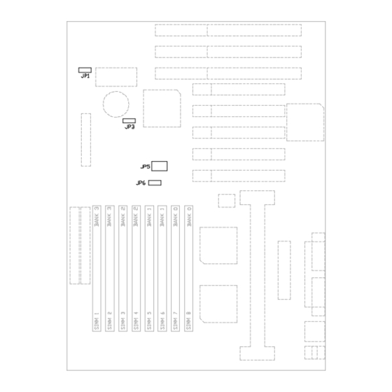
CHAPTER 1 INTRODUCTION Preface The motherboard is a 4-layer, full ATX form factor high-performance mainboard. It is developed around the Pentium II processor with 64 bit access to data transfer and MMX technology. It includes Intel i82440FX system chipset, NS PC87308 Super I/O controller. Features Processor Intel Pentium II series. - Page 8 Chapter 1 Fig. 1 Key Components of the Mainboard...
- Page 9 Introduction Form Factor Full ATX Size (305 x 244mm) 4 Layer Environment Working Specifications Actual Field MTBF (hours) 104,515 hours Preventive Maintenance Not Required Environmental Limits Operating Non-operating Temperature 0 to 50 degree Celsius -10 to 65 Degree Celsius Relative Humidity (without condensation) 8 to 85% 5 to 95%...
- Page 10 Chapter 1...
-
Page 11: Jumper Settings
CHAPTER 2 JUMPER SETTINGS JUMPERS PRESENTATION Pins 1 and 2 are shorted with a jumper cap. Pins 2 and 3 are shorted with a jumper cap. The jumper is closed (on) when the jumper cap is placed over the two pins of the jumper. The jumper is open (off) when the jumper cap is removed from jumper. -
Page 12: Graphical Description Of Jumper Settings
Chapter 2 GRAPHICAL DESCRIPTION OF JUMPER SETTINGS Fig. 2 Jumper Location... -
Page 13: Cpu Speed
Jumper Settings CPU SPEED 233MHz Fig. 3a CPU Speed 266MHz Fig. 3b CPU Speed 300MHz Fig. 3c CPU Speed... -
Page 14: Jp3 - Clear Cmos Rtc Data
Chapter 2 JP3 - CLEAR CMOS RTC DATA JP3 is used to clear the content of the CMOS data in the RTC chip. Refer to the Fig. 12 for the location. Table 1: JP3 - Clear CMOS RTC Data JP1 - VOLTAGE SELECTION FOR SYSTEM 5V Flash EPROM on System ROM Fig. - Page 15 Jumper Settings 12V Flash EPROM on System ROM Fig. 4b...
-
Page 16: Retention Mechanism Kits Installation Guide
Chapter 2 RETENTION MECHANISM KITS INSTALLATION GUIDE Retention Mechanism Kits includes following components: Retention mechanism Assembly Fig. 5 Retention Mechanism Attach Mount Fig. 6... - Page 17 Jumper Settings Heatsink Top Support Fig. 7 Heatsink Support Base Fig. 8 Before the installation of RM Kits find the six holes on the motherboard for RM installation. The hole position and usage is as following: Fig. 9...
- Page 18 Chapter 2 Installation Guide Mount the two RM Attach Mounts onto the motherboard from bottom side. These mounts will be used to attach the RM Assembly. Put the RM Assembly on the Slot 1 and use the four screws to fix RM Assembly to the RM Attach Mount.
-
Page 19: Memory Configuration
Jumper Settings Insert the Heatsink Top Support to the Pentium II Heatsink and the Heatsink Support Base as the following diagram: Fig. 11 MEMORY CONFIGURATION The Mainboard lets user upgrade system memory via SIMM sockets on the mainboard. On-board memory is located in three banks: Bank 0, Bank 1, Bank 2 and Bank 3. Two SIMM sockets are provided in each bank. - Page 20 Chapter 2 Install memory in any or all of the banks in any combination as following: Bank 0 (SIMM7, 8) 4M, 8M, 16M, 32M or 64M Bank 1 (SIMM5, 6) 4M, 8M, 16M, 32M or 64M Bank 2 (SIMM3, 4) 4M, 8M, 16M, 32M or 64M Bank 3 (SIMM1, 2) 4M, 8M, 16M, 32M or 64M...
-
Page 21: Connector Configuration
CHAPTER 3 CONNECTOR CONFIGURATION Once the mainboard have been fastened into the system case, the next step is to connect the internal cables and external cables. The mainboard connectors have varying numbers of pins and are the points of contact between the mainboard and other parts of the computer. Fig. -
Page 22: J1 - Multiple Function Jumper
Chapter 3 J1 - MULTIPLE FUNCTION JUMPER J1 is a front panel multi-function jumper include speaker, reset, keylock, Hard Disk LED, Hardware Suspend Switch, ATX power switches and Turbo LED. Fig. 13 J1 - Multiple Function Jumper The pin definition is as following table: Description Description Not Used... -
Page 23: J2 - Irda Connector
Connector Configuration J2 - IrDA CONNECTOR J2 is a IrDA connector that use UART2 as interface of IrDA Infrared and SIR. Fig. 14 J2 - IrDA Connector J10 - SLOT 1 FOR PENTIUM CPU J10 is the slot for Pentium II CPU. Fig. -
Page 24: J11 - Atx Power Supply Connector
Chapter 3 J11 - ATX POWER SUPPLY CONNECTOR Fig. 16 J11 - ATX Power Supply Connector J3 - FLOPPY DRIVE CONNECTOR This connector supports the floppy drive ribbon cable. After connecting the single end to the board, connect the two plugs on the other end to the floppy drive. J7, J8 - PRIMARY/SECONDARY IDE CONNECTORS These connectors support the provided IDE hard disk ribbon cable. -
Page 25: Ps/2 Keyboard Connector
Connector Configuration PS/2 KEYBOARD CONNECTOR This connector is a six-pin female mini DIN connector using a PS/2 plug. If a standard AT size keyboard plugs, you may use the DIN to mini DIN adaptor. PS/2 MOUSE CONNECTOR This connector is a six-pin female mini DIN connector using a PS/2 plug. Plug the jack on the PS/2 keyboard cable into this connector. - Page 26 Chapter 3...
-
Page 27: Ami Winbios Setup
CHAPTER 4 AMI WinBIOS SETUP WinBIOS Setup has an easy-to-use graphical user interface that makes system configuration easy and simple. The configuration options in WinBIOS Setup are all icon-based. All settings for each option are displayed for easy access. All WinBIOS Setup functions can be accessed by mouse, keyboard, or pen. -
Page 28: Using Keyboard With Winbios Setup
Chapter 4 USING KEYBOARD WITH WinBIOS SETUP WinBIOS Setup has a built-in keyboard driver that uses simple keystroke combinations: Keystroke Function <Tab> Move to the next window or field. ? , ? , ? , ? Move to the next field to the right, left, above, or below. <Enter>... -
Page 29: Winbios Setup Main Menu
AMI WinBIOS Setup WinBIOS SETUP MAIN MENU The WinBIOS Setup main menu, shown below, is organized into four windows. Each windows corresponds to a section. Fig. 18 Main Menu Each section contains several icons. Clicking on each icon activates a specific function. The sections are: Setup contains six icons that permit user to set system configuration options such as... -
Page 30: Setup
Chapter 4 Each WinBIOS Setup option has two default settings. The type of default are: Optimal these settings provide the best performance characteristics. Fail-Safe these settings are more likely to configure a workable computer when something is wrong. If user cannot boot the computer successfully, select the Fail-Safe WinBIOS setup options and try to diagnose the problem after the computer boots. -
Page 31: Standard Setup
AMI WinBIOS Setup 4.6.1 STANDARD SETUP The Standard Setup Screen follows. Fig. 19 Standard Setup Menu The following are the description for the options located in the Standard Setup window. Configuring IDE Drives: If the hard disk drive to be configured is an IDE drive, select the appropriate drive icon (Pri Master, Pri Slaves, Sec Master, Sec Slave). -
Page 32: Advanced Setup
Chapter 4 Click on PIO Mode to select the IDE Programmed I/O mode. The setting are Auto, 0, 1, 2, 3, 4, or 5. Click on Auto to allow AMIBIOS to automatically choose the PIO mode that the IDE drive being configured uses. If you select 0 -5 you must make absolutely certain that you are selecting the PIO mode supported by the IDE drive being configured. - Page 33 AMI WinBIOS Setup Quick Boot: Set this option to Enabled to instruct AMIBIOS to boot quickly when the computer is powered on. The settings are: Setting Description Disabled AMIBIOS test all system memory. AMIBIOS waits up to 40 seconds for a READY signal from the IDE hare disk drive.
- Page 34 Chapter 4 S.M.A.R.T. for Hard Disks: This is the Self-Monitoring Analysis and Reporting Technology. This feature helps BIOS warn the user of the possible device failure thereby giving user a chance to back up the device and replace the device before actual failure happens. BootUp NumLock: Set this option to Off to turn the Num Lock key off when the computer is booted so you can use the arrow keys on both the numeric keypad and the keyboard.
- Page 35 AMI WinBIOS Setup Internal Cache: This option specifies the caching algorithm used for L1 internal cache memory. The settings are: Setting Description Disabled Neither L1 internal cache memory on the CPU or L2 secondary cache memory is enabled. WriteBack Use the write-back caching algorithm. (default) WriteThru Use the write-through caching algorithm.
- Page 36 Chapter 4 C000,16K Shadow/C400,16K Shadow/C800,16K Shadow/CC00,16K Shadow/ D000,16K Shadow/D400,16K Shadow/D800,16K Shadow: These options control the location of the contents of the 16KB of ROM beginning at the specified memory location. If no adaptor ROM is using the named ROM area, this area is made available to the local bus. The settings are: Setting Description...
-
Page 37: Chipset Setup
AMI WinBIOS Setup 4.6.3 CHIPSET SETUP The Chipset Setup options described in this section are the standard options as shown on the following screen. Fig. 21 Chipset Setup Menu Auto Configure DRAM Timing: Specify the method of configuring DRAM timing. Enabled Set the DRAM Timing Parameter according to the DRAM speed. - Page 38 Chapter 4 DRAM Read Burst Timing (B/E/F): The DRAM read burst timing depend on the type of DRAM on a per-row basis. Slower rates may be required to support slower memories. The setting are x1/2/3, x2/2/3, x2/3/4 and x3/4/4. The Optimal default setting is x2/3/4. The Fail- Safe default setting is x3/4/4.
- Page 39 AMI WinBIOS Setup PCI To DRAM Pipeline : DRAM optimization feature: If Enabled, full PCI-to-DRAM write pipelining is enabled. Buffers in the chipset store data written from the PCI bus to memory. When Disabled, the writes are not buffered and the CPU must wait until the write is complete before starting another write cycle.
-
Page 40: Power Management Setup
Chapter 4 4.6.4 POWER MANAGEMENT SETUP The Power Management Setup options described in this section are the standard options as shown on the following screen. Fig. 22 Power Management Setup Menu Power Management/APM: Set this option to Enabled to enable the power management and APM (Advanced Power Management) features. - Page 41 AMI WinBIOS Setup Hard Disk Power Down Mode: This option specifies the power management state that the hard disk drive enters after the specified period of display inactivity has expired. The settings are Disabled, Standby or Suspend. The default settings are Disabled. Hard Disk Timeout (Minute): This option specifies the length of a periods of hard disk inactivity.
-
Page 42: Pci/Pnp Setup
Chapter 4 4.6.5 PCI/PnP SETUP PCI/PnP Setup options are displayed by choosing the PCI/PnP Setup Icon from the Setup Menu. The standard option is shown on the following screen. Fig. 23 PCI/PnP Setup Menu Plug and Play Aware OS: Set this option to Yes if the operating system installed in the computer is Plug and Play-aware. - Page 43 AMI WinBIOS Setup PCI Latency Timer (PCI Clocks): This option sets latency of all PCI devices on the PCI bus. The settings are in units equal to PCI clocks. The settings are 32, 64, 96, 128, 160, 192, 224, or 248. The Optimal and Fail-Safe default settings are 64. PCI VGA Palette Snoop: This option must be set to Enabled if any ISA adapter card installed in the computer requires VGA palette snooping.
-
Page 44: Peripheral Setup
Chapter 4 IRQ3/IRQ4/IRQ5/IRQ7/IRQ9/IRQ10/IRQ11/IRQ12/IRQ14/IRQ15: These options specify the bus that the named interrupt request lines (IRQs) are used on. These options allow you to specify IRQs for use by legacy ISA adapter cards. These options determine if AMIBIOS should remove an IRQ from the pool of available IRQs passed to BIOS configurable devices. - Page 45 AMI WinBIOS Setup Onboard Serial Port1: This option enables serial port 1 on the motherboard and specifies the base I/O port address for serial port 1. The settings are 3F8h, 2F8h, 3E8h, 2E8h, Disabled or Auto. The Optimal and Fail-Safe default settings are Auto.
-
Page 46: Security
Chapter 4 Parallel Port IRQ: This option is only available if the setting for the Onboard Parallel Port option is a 378h, 278h or 3BCh. The settings are 5 or 7. Parallel Port DMA Channel: This option is only available if the setting for the Parallel Port Mode option is ECP. -
Page 47: Changing A Password
AMI WinBIOS Setup You can enter a password by: typing the password on the keyboard, selecting each letter via the mouse, or selecting each letter via the pen stylus. Pen access must be customized for each specific hardware platform. When you select Supervisor or User, AMIBIOS prompts for a password. You must set the Supervisor password before you can set the User password. - Page 48 Chapter 4 Fig. 26 Anti Virus Menu The settings are Enabled or Disabled. If enabled, the following appears when a write is attempted to the boot sector. User may have to type N several times to prevent the boot sector write.
-
Page 49: Utility
AMI WinBIOS Setup UTILITY The following icons appear in this section: ?? Color set, and ?? Language. Color Set Color Set sets the WINBIOS Setup screen colors. Fig. 27 Color Set Menu Language Language allows you to select English, German, or French language screen prompts and messages. - Page 50 Chapter 4 DEFAULT The icons in this section permit user to select a group of settings for all WinBIOS Setup options. Not only can use these icons to quickly set system configuration parameters, user can choose a group of settings that have a better chance of working when the system is having configuration-related problems.
- Page 51 CHAPTER 5 FLASH MEMORY UTILITY Make sure the system is running in real mode. This utility will not operate if the system is under protected mode or virtual mode. This means that you cannot reprogram the motherboard BIOS under the Windows environment or with any memory management software, including HIMEM.SYS.
- Page 52 Chapter 5...
- Page 53 APPENDIX 1 QUICK GUIDE The table below summaries the CPU frequence and settings of each jumper of the motherboard. CPU Type Freq. Ration Bus Freq. Rating Setting Bus Freq. Setting Pentium II 233MHz 3.5x 66MHz JP5: 1-2 close JP6: 1-2 close 3-4 close 5-6 open 7-8 open...
- Page 54 Quick Guide...
- Page 55 Appendix A...
- Page 56 Quick Guide...
Need help?
Do you have a question about the PRM-0074I and is the answer not in the manual?
Questions and answers