Advertisement
Quick Links
ISL78229EV1Z
Evaluation Board User Guide
Description
The ISL78229EV1Z board demonstrates the 2-phase
synchronous boost operation and PMBus™ functionalities of
the ISL78229. It verifies the high efficiency of synchronous
boost operation and all the features of the IC including input
Constant Current (CC) control, analog/digital tracking, diode
emulation, phase dropping, PMBus™ functions, etc.
Specifications
This board has been configured and optimized for the following
operating conditions. Refer to
more detailed descriptions.
• VIN_MIN = 7.5V (or lower, refer to
• VIN_TYP = 12V
• VIN_MAX = 30V (typical)
• VOUT = 36V (typical)
• IOUT_MAX = 12A (typical)
• IIN_AVG_MAX = 41.5A (typical)
• f
= 200kHz
SW
Ordering Information
PART NUMBER
ISL78229EV1Z
ISL78229 Evaluation Board, ZLUSBEVAL3Z
adapter, USB cable
T1: VIN
T2: GND
J29
UG065 Rev 1.00
January 6, 2016
"Operating Range" on page 3
for
"Operating
Range")
DESCRIPTION
J1
VIN
EN
NTC
PMBus
signals
SDA
J50
SCL
SALERT
VCC
J7
TRACK
ISL78229
VCC
ATRK/DTRK
J17
VCC
HIC/LATCH
J18
VCC
J23
DE/PHDRP
FIGURE 1. ISL78229EV1Z BLOCK DIAGRAM
Key Features
• Input/output voltage withstands 55V DC and 60V transients
• Input average Constant Current (CC) control loop
• PWM and analog track functions
• Forced PWM operation with negative current limiting
• External synchronization
• Selectable Continuous Conduction Mode (CCM), Diode
Emulation (DE) and Phase Dropping (PH_DROP) modes
• Comprehensive protections
• Selectable Hiccup or Latch-off fault responses
2
• I
C/PMBus™ compatible digital interface to control/monitor
operation parameters
• Boards can be stacked for parallel operations
• Monitoring test points for key signals
References
•
ISL78229
Datasheet
• AN1900, "USB to PMBus™ Adapter User Guide"
•
PowerNavigator™ Software
•
PowerNavigator User Guide
VCC
VCC
SGND
PVCC
PVCC
PGND
BOOT1
UG1
R
SEN1
PH1
LG1
ISEN1N
ISEN1P
BOOT2
UG2
R
SEN2
PH2
LG2
ISEN2N
ISEN2P
FB
USER'S MANUAL
January 6, 2016
T3: VOUT
T4: GND
Page 1 of 32
UG065
Rev 1.00
Advertisement

Related Manuals for Renesas ISL78229EV1Z


Summary of Contents for Renesas ISL78229EV1Z
- Page 1 Rev 1.00 January 6, 2016 Description Key Features The ISL78229EV1Z board demonstrates the 2-phase • Input/output voltage withstands 55V DC and 60V transients synchronous boost operation and PMBus™ functionalities of • Input average Constant Current (CC) control loop the ISL78229. It verifies the high efficiency of synchronous •...
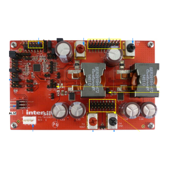
- Page 2 TO CONNECT J39: OPTIONAL CONNECTOR FOR PMBus™ SIGNALS POWER VOUT AND GND FIGURE 2. TOP VIEW OF THE ISL78229EV1Z J57: FOR BOARD STACK TO CONNECT CONTROL SIGNALS J52: FOR BOARD STACKING TO CONNECT POWER VIN AND GND J53: FOR BOARD STACKING TO CONNECT POWER VOUT AND GND FIGURE 3.
-
Page 3: Recommended Equipment
Functional Description control) • f = 200kHz The ISL78229EV1Z evaluation board pictures are shown in • The board is set in CCM mode by default with J23’s Pin 2 Figures 2 and 3. The board supports a quick evaluation of various (DE/PHDRP) shorted to Pin 3 (GND) by the jumper. - Page 4 J23. (OC1) can be changed by replacing the current sense resistor 1. CCM mode - The ISL78229EV1Z board is set in CCM mode by ) and/or current sense gain setting resistors R default with J23’s Pin 2 (DE/PHDRP) shorted to Pin 3 (GND) ) for the respective phases.
- Page 5 ISL78229EV1Z (controlled by the CC loop) and the V continues to drop. The 3. DE mode - Short J23’s Pin 2 (DE/PHDRP) and Pin 3 (VCC) with heavier the load, the lower the V , which is the characteristic a jumper to set the IC in DE Mode. Leave J23 Pin 1 (GND)
- Page 6 UNNAM ED_1_JUM PER3_I384_IN2 UNNAM ED_1_SM CAP_I142_A DRAWING TITLE SALERT DRAWN BY: DATE: SCHEMATIC TIM KLEMANN 08/11/2015 SALERT VI2C_EXT EVALUATION BOARD ENGINEER: JUN LIU ISL78229 DE/PHDRP SIZE DRAWING NO. REV. ISL78229EV1Z $CDS_IMAGE|intersil_color_sm2_0.jpg|1655|334 SHEET FILENAME: ~/ISL78229/ISL78229EV1ZE FIGURE 4. ISL78229EV1Z BOARD SCHEMATIC - PAGE 1...
- Page 7 ISL78229EV1Z Schematic (Continued) VOUT ESQ-108-33-L-D TSM-108-03-L-DV TSM-110-03-L-DV ESQ-110-33-L-D FIGURE 5. ISL78229EV1Z BOARD SCHEMATIC - PAGE 2...
- Page 8 J52 (socket type) to connect both boards’ power inputs (VIN and GND) together. FIGURE 6. STACK TWO ISL78229EV1Z FOR PARALLEL OPERATION TO ACHIEVE 4-PHASE INTERLEAVED BOOST REGULATOR (VIEW FROM INPUTS SIDE) Bottom board’s J55 (header/pin type) plugged into top board’s J53 (socket type) to...
- Page 9 CONNECT THE ZLUSBEVAL3Z DONGLE CABLE TO HOST PC CONNECT THE ZLUSBEVAL3Z DONGLE TO J50 OF THE ISL78229EV1Z FIGURE 8. ISL78229EV1Z CONNECTED TO INTERSIL DONGLE FOR GUI (TOP VIEW) FIGURE 9. ISL78229EV1Z CONNECTED TO INTERSIL DONGLE FOR GUI (BOTTOM VIEW) UG065 Rev 1.00...
-
Page 10: Pcb Layout Guidelines
10. Launch the PowerNavigator™ software. 10. Keep the driver traces as short as possible and with relatively 11. Monitor and configure the ISL78229EV1Z board using the large width (25 mil to 40 mil is recommended) and avoid PMBus™ commands in the evaluation software. - Page 11 ISL78229EV1Z TABLE 1. CONNECTOR/MONITOR-PIN DESCRIPTIONS CONNECTOR /TEST POINT SIGNAL NAME DESCRIPTION Positive power input terminal for the boost regulator input. Power ground input terminal for the boost regulator input. VOUT Positive power output terminal for the boost regulator output. Power ground output terminal for the boost regulator output.
- Page 12 ISL78229EV1Z TABLE 1. CONNECTOR/MONITOR-PIN DESCRIPTIONS (Continued) CONNECTOR /TEST POINT SIGNAL NAME DESCRIPTION GND (Pin 1), EN (Pin 2), Pin 3 (For VIN_UVLO) Enable/Disable options. Pin 2 (EN) can be used to apply external signal to enable and disable the IC.
-
Page 13: Bill Of Materials
ISL78229EV1Z TABLE 1. CONNECTOR/MONITOR-PIN DESCRIPTIONS (Continued) CONNECTOR /TEST POINT SIGNAL NAME DESCRIPTION Pin 1: TRACK Socket type connector on the board’s bottom side for connections of the signals needed for the boards’ parallel operation. With it being plugged by Pins 5-12 of J56 (header/pin Pin 2: FSYNC if J56 Pin 1 and Pin 2 shorted type connector) of the other board, the two boards’... - Page 14 ISL78229EV1Z Bill of Materials (Continued) REFERENCE MANUFACTURER DESIGNATOR PART NUMBER MANUFACTURER DESCRIPTION ESQ-108-33-L-D SAMTEC Connector-Socket, ELEVATED, Through-Hole, 2x8, DUALROW, 2.54mm Pitch, ROHS TSM-110-03-L-DV SAMTEC Connector-Header, SMD, 2x10, 2.54mm Pitch, VERTICAL, ROHS TSM-108-03-L-DV SAMTEC Connector-Header, SMD, 2x8, 2.54mm Pitch, VERTICAL, ROHS...
- Page 15 ISL78229EV1Z Bill of Materials (Continued) REFERENCE MANUFACTURER DESIGNATOR PART NUMBER MANUFACTURER DESCRIPTION R6, R16, R17, R18 Various Various Resistor, SMD, 0603, 10kΩ, 1%, ROHS R7, R9, R19, R21 Various Various Resistor, SMD, 0603, 51.1Ω, 1%, ROHS R8, R10, R20, R22...
-
Page 16: Board Layout
ISL78229EV1Z Board Layout FIGURE 12. TOP COMPONENT ASSEMBLY UG065 Rev 1.00 Page 16 of 32 January 6, 2016... - Page 17 ISL78229EV1Z Board Layout (Continued) FIGURE 13. TOP SILKSCREEN AND PIN PADS UG065 Rev 1.00 Page 17 of 32 January 6, 2016...
- Page 18 ISL78229EV1Z Board Layout (Continued) FIGURE 14. TOP LAYER UG065 Rev 1.00 Page 18 of 32 January 6, 2016...
- Page 19 ISL78229EV1Z Board Layout (Continued) FIGURE 15. 2 LAYER UG065 Rev 1.00 Page 19 of 32 January 6, 2016...
- Page 20 ISL78229EV1Z Board Layout (Continued) FIGURE 16. 3 LAYER UG065 Rev 1.00 Page 20 of 32 January 6, 2016...
- Page 21 ISL78229EV1Z Board Layout (Continued) FIGURE 17. 4 LAYER UG065 Rev 1.00 Page 21 of 32 January 6, 2016...
- Page 22 ISL78229EV1Z Board Layout (Continued) FIGURE 18. 5 LAYER UG065 Rev 1.00 Page 22 of 32 January 6, 2016...
- Page 23 ISL78229EV1Z Board Layout (Continued) FIGURE 19. BOTTOM LAYER UG065 Rev 1.00 Page 23 of 32 January 6, 2016...
- Page 24 ISL78229EV1Z Board Layout (Continued) FIGURE 20. BOTTOM SILKSREEN AND PIN PADS UG065 Rev 1.00 Page 24 of 32 January 6, 2016...
- Page 25 ISL78229EV1Z Board Layout (Continued) FIGURE 21. BOTTOM SILKSREEN AND PIN PADS (MIRRORED) UG065 Rev 1.00 Page 25 of 32 January 6, 2016...
-
Page 26: Performance Curves
ISL78229EV1Z Performance Curves Unless otherwise specified, operating conditions for the oscilloscope waveforms are V = 12V, V = 36V and T = +25°C 1.0V/DIV WITH 36V OFFSET 5.0A/DIV DE WITH PHASE DROP DE WITHOUT PHASE DROP PH1 30.0V/DIV 0.01 0.10 1.00... - Page 27 ISL78229EV1Z Performance Curves Unless otherwise specified, operating conditions for the oscilloscope waveforms are V = 12V, V = 36V and T = +25°C (Continued) 20.0V/DIV PVCC 2.0V/DIV PGOOD 5.0V/DIV PGOOD 3.0V/DIV PH1 30.0V/DIV SS 2.0V/DIV SS 3.0V/DIV PH1 30.0V/DIV 5ms/DIV 20ms/DIV FIGURE 28.
- Page 28 ISL78229EV1Z Performance Curves Unless otherwise specified, operating conditions for the oscilloscope waveforms are V = 12V, V = 36V and T = +25°C (Continued) 10.0V/DIV PGOOD 4.0V/DIV 1.0V/DIV WITH 36V OFFSET PH2 20.0V/DIV PH2 30.0V/DIV PH1 20.0V/DIV PH1 30.0V/DIV 5µs/DIV 2µs/DIV...
- Page 29 ISL78229EV1Z Performance Curves Unless otherwise specified, operating conditions for the oscilloscope waveforms are V = 12V, V = 36V and T = +25°C (Continued) FB 300mV/DIV FB 300mV/DIV 6.8V/DIV 6.8V/DIV TRACK 300mV/DIV TRACK 300mV/DIV PH1 20.0V/DIV PH1 20.0V/DIV 2ms/DIV 2ms/DIV FIGURE 40.
- Page 30 ISL78229EV1Z Performance Curves Unless otherwise specified, operating conditions for the oscilloscope waveforms are V = 12V, V = 36V and T = +25°C (Continued) TRACK 4.0V/DIV 2.0V/DIV WITH 36V OFFSET 1.0V/DIV WITH 28V OFFSET I_LOAD 5.0A/DIV PH2 40.0V/DIV PH1 30.0V/DIV PH2 30.0V/DIV...
- Page 31 ISL78229EV1Z Performance Curves Unless otherwise specified, operating conditions for the oscilloscope waveforms are V = 12V, V = 36V and T = +25°C (Continued) PH1 40.0V/DIV PH1 30.0V/DIV PH2 40.0V/DIV PH2 30.0V/DIV 5.0V/DIV WITH 36V OFFSET 10.0V/DIV SDA 4.0V/DIV SDA 4.0V/DIV...
- Page 32 10. It is the responsibility of the buyer or distributor of Renesas Electronics products, or any other party who distributes, disposes of, or otherwise sells or transfers the product to a third party, to notify such third party in advance of the contents and conditions set forth in this document.
Need help?
Do you have a question about the ISL78229EV1Z and is the answer not in the manual?
Questions and answers