Table of Contents
Advertisement
Quick Links
ISL34341KIT1Z, ISL76321ARZ-EVAL1Z
Evaluation Kit
Overview
This manual covers both the ISL34341 and ISL76321
evaluation kits. These kits enable the user to exercise the
SerDes in a lab environment and to see the high speed and
parallel signals conveniently on an oscilloscope. Contents of
the kit are shown in Figure 1.
Schematics and a software GUI can be downloaded from:
http://www.intersil.com/data/EV/ISL34341_Eval_Kit_Software.zip
CAT5 CABLES FOR POWER
AND I
AN1455 Rev. 2.00
Jan 31, 2011
2
C TO EVBS
FIGURE 1. KIT CONTENTS
USER'S MANUAL
There are slight differences between the ISL34341 and
ISL76321 kits. The ISL76321 uses a Molex cable instead of
Rosenberger which the ILS34341 uses. Unless specifically
mentioned, ISL76321 can be substituted anywhere you see
ISL34341.
DESERIALIZER EVB
INTERFACE BOARD
SERIALIZER EVB
AN1455
Rev. 2.00
Jan 31, 2011
ROSENBERGER
CABLE FOR HS
SERIAL TRAFFIC
USB CABLE TO
PC
Page 1 of 14
Advertisement
Table of Contents

Related Manuals for Renesas ISL34341KIT1Z


Summary of Contents for Renesas ISL34341KIT1Z
-
Page 1: Overview
USER’S MANUAL ISL34341KIT1Z, ISL76321ARZ-EVAL1Z AN1455 Evaluation Kit Rev. 2.00 Jan 31, 2011 Overview There are slight differences between the ISL34341 and ISL76321 kits. The ISL76321 uses a Molex cable instead of This manual covers both the ISL34341 and ISL76321 Rosenberger which the ILS34341 uses. Unless specifically evaluation kits. -
Page 2: Table Of Contents
ISL34341KIT1Z, ISL76321ARZ-EVAL1Z Table of Contents Overview ....................1 Nomenclature. -
Page 3: Nomenclature
ISL34341KIT1Z, ISL76321ARZ-EVAL1Z TABLE 1. NOMENCLATURE SHORTHAND REFERS TO: WHY SO SPECIFIC? ser.PCLK_IN PCLK_IN device pin. We are referring to the device pin specifically and not the SerDes is in video serializer mode. BNC connector. There are several paths on the EVB to the device pin. -
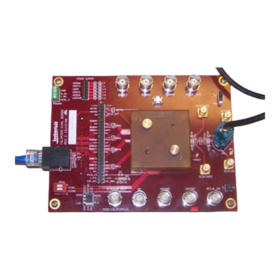
Page 4: Evaluation Board
ISL34341KIT1Z, ISL76321ARZ-EVAL1Z 1k PROBES J20 CMOS (SENSE OUTS) PARALLEL VIDEO SS2 SerDes GENDER IN/OUT SWITCH RESET POWER AND I C FROM INTERFACE BOARD P2 SERIOP/N SS6 I C ADDRESS SWITCH desEVB.REFCLK INPUT SYNC POLARITY AND I 1k PROBES serEVB.PCLK SENSE OUT... -
Page 5: Bnc Sense Outputs (Built-In 1K Probes)
ISL34341KIT1Z, ISL76321ARZ-EVAL1Z BNC SENSE OUTPUTS (BUILT-IN 1k PROBES) DesEVB.PCLK_IN BNC Critical signals are “probed” by 950Ω resistors and brought to The PCLK_IN BNC is not terminated for compatibility reasons and BNC and SMA connectors. When connected to a scope set to 50Ω... -
Page 6: Interface Board
ISL34341KIT1Z, ISL76321ARZ-EVAL1Z N O C O N N E C T 3 .3 V G N D T O P C U S B P O R T TO E V A L B O A R D S R E M O V E AL L TH E S E... -
Page 7: Setup
ISL34341KIT1Z, ISL76321ARZ-EVAL1Z Setup Evaluation Board Setup DESERIALIZER EVB LCD PANEL 50-PIN RIBBON FUNCTION 3.3V DC GENERATOR SUPPLY RAW RGB 50-PIN RIBBON GENERATOR SERIALIZER EVB FIGURE 4. MAIN SETUP CONNECTIONS • Raw RGB generator to serEVB.J20 through user’s ribbon cable It is almost redundant to mention that in this system, if any of the components are not working properly, or not connected, the •... -
Page 8: Vsync/Hsync Polarity Setup
ISL34341KIT1Z, ISL76321ARZ-EVAL1Z VSYNC/HSYNC Polarity Setup PCLK Polarity Setup For the serializer to transport video properly, it must know the A grainy or intermittent image is usually due to improper PCLK polarity of the VSYNC and HSYNC signals supplied by the RGB polarity. -
Page 9: Quickstart
ISL34341KIT1Z, ISL76321ARZ-EVAL1Z Quickstart 1. Scope settings • All channels 100mV/div., DC 50Ω coupling. Assuming a raw RGB source is hooked up to J20, this section • Time base 100ns/div. provides a sample startup procedure. • Trigger on rising edge of Ch3 (ser.VSYNC) TABLE 4. -
Page 10: Gui Usage
ISL34341KIT1Z, ISL76321ARZ-EVAL1Z GUI Usage • Open the GUI, double click “Intersil_I2C_Comm_V316.exe”. • Load the register map definition file: ISL34341_Serializer.isl Open two instances of the GUI so that one controls the serializer (File->Open->Comm Register Definitions) and another the deserializer. The two GUIs will communicate •... - Page 11 ISL34341KIT1Z, ISL76321ARZ-EVAL1Z • Open a second GUI “Intersil_I2C_Comm_V316.exe” All cells in this tool can be saved to an ascii file and later recalled. This is how the default templates were generated. To save all the • Load a register map definition ISL34341_Deserializer.isl cells click on the “File”...
-
Page 12: Prbs Gui Setups
ISL34341KIT1Z, ISL76321ARZ-EVAL1Z PRBS GUI Setups Figure 8 and Figure 9 show the GUI setup for the serializer and deserializer when running the PRBS. The PRBS setup condition changes from the register defaults are shown inside red circles. The error count is an 8 bit value read in the deseralizer register 0x07 and is circled in green. - Page 13 ISL34341KIT1Z, ISL76321ARZ-EVAL1Z FIGURE 9. DESERIALIZER CONFIGURATION It is important to monitor the clock output and status pin on the To return to normal video you can program the register values deserializer in addition to the error count in 0x07. This ensures back to their previous values or simply do a reset of both chips.
- Page 14 10. It is the responsibility of the buyer or distributor of Renesas Electronics products, or any other party who distributes, disposes of, or otherwise sells or transfers the product to a third party, to notify such third party in advance of the contents and conditions set forth in this document.
Need help?
Do you have a question about the ISL34341KIT1Z and is the answer not in the manual?
Questions and answers